Tractatenblad van het Koninkrijk der Nederlanden
| Datum publicatie | Organisatie | Jaargang en nummer | Rubriek | Datum totstandkoming |
|---|---|---|---|---|
| Ministerie van Buitenlandse Zaken | Tractatenblad 2008, 87 | Verdrag |
U bent nu hier: Publicaties Officiële publicaties
Zoals vergunningen, bouwplannen en lokale regelgeving.
Adressen en contactpersonen van overheidsorganisaties.

Internationaal Verdrag voor de beveiliging van mensenlevens op zee, 1974;
(met Bijlage)
Londen, 1 november 1974
De Engelse en de Franse tekst van Verdrag en Bijlage zijn geplaatst in Trb. 1976, 157.
Voor correcties van de Bijlage zie Trb. 1983, 32.
Voor wijzigingen van de Bijlage zie Trb. 1983, 32 en rubriek J van Trb. 1983, 173, Trb. 1985, 155, Trb. 1989, 42 en 98, Trb. 1992, 24, Trb. 1994, 19, Trb. 1996, 18, 128 en 257, Trb. 1997, 226, Trb. 1998, 155, en Trb. 2005, 55.
Voor correcties van de wijzigingen van de Bijlage zie Trb. 1985, 155, rubriek J van Trb. 1995, 236, rubriek B van Trb. 1996, 128, rubriek J van Trb. 2005, 55 en rubriek B van Trb. 2006, 72.
Resolutie MSC.151(78) van 20 mei 2004
Bij Resolutie MSC.151(78) heeft de Maritieme Veiligheidscommissie van de Internationale Maritieme Organisatie op 20 mei 2004 in overeenstemming met artikel VIII(b)(iv) van het Verdrag wijzigingen aangenomen. De Engelse tekst1) van de Resolutie en de wijzigingen luidt als volgt:
(adopted on 20 May 2004)
Adoption of Amendments to the International Convention for the Safety of Life at Sea, 1974, as amended
The Maritime Safety Committee,
Recalling Article 28(b) of the Convention on the International Maritime Organization concerning the functions of the Committee,
Recalling further article VIII(b) of the International Convention for the Safety of Life at Sea (SOLAS), 1974 (hereinafter referred to as “the Convention”), concerning the amendment procedure applicable to the Annex to the Convention, other than to the provisions of chapter I thereof,
Noting SOLAS regulation II-1/3-6 concerning access to and within spaces in the cargo area of oil tankers of 500 gross tonnage and over and bulk carriers of 20,000 gross tonnage and over, adopted by resolution MSC.134(76), which is applicable to oil tankers and bulk carriers constructed on or after 1 January 2005,
Acknowledging concerns expressed with regard to problems which might be encountered when implementing the requirements of the aforementioned SOLAS regulation II-1/3-6,
Having considered, at its seventy-eighth session, amendments to SOLAS regulation II-1/3-6, proposed and circulated in accordance with article VIII(b)(i) of the Convention,
1. Adopts, in accordance with article VIII(b)(iv) of the Convention, amendments to regulation II-1/3-6 of the Convention, the text of which is set out in the Annex to the present resolution;
2. Determines, in accordance with article VIII(b)(vi)(2)(bb) of the Convention, that the said amendments shall be deemed to have been accepted on 1 July 2005, unless, prior to that date, more than one third of the Contracting Governments to the Convention or Contracting Governments the combined merchant fleets of which constitute not less than 50% of the gross tonnage of the world’s merchant fleet, have notified their objections to the amendments;
3. Invites SOLAS Contracting Governments to note that, in accordance with article VIII(b)(vii)(2) of the Convention, the amendments shall enter into force on 1 January 2006 upon their acceptance in accordance with paragraph 2 above;
4. Requests the Secretary-General, in conformity with article VIII(b)(v) of the Convention, to transmit certified copies of the present resolution and the text of the amendments contained in the Annex to all Contracting Governments to the Convention;
5. Further requests the Secretary-General to transmit copies of this resolution and its Annex to Members of the Organization, which are not Contracting Governments to the Convention;
6. Resolves that SOLAS Contracting Governments may apply, in advance, the annexed SOLAS regulation II-1/3-6 adopted by this resolution together with the amendments to the Technical provisions for means of access for inspections adopted by resolution MSC.158(78) in lieu of SOLAS regulation II-1/3-6 adopted by resolution MSC.134(76) and the Technical provisions for means of access for inspections adopted by resolution MSC.133(76) to ships flying their flag constructed on or after 1 January 2005.
1. The title of the regulation is replaced by the following:
“Access to and within spaces in, and forward of, the cargo area of oil tankers and bulk carriers”
2. In paragraph 1.1, the date “1 January 2005” is replaced with “1 January 2006”.
3. In paragraph 2.1, in the first sentence, the words “within the cargo area” and “a permanent” are deleted.
4. In paragraph 3.1, in the second sentence, the words “or to foreward ballast tanks” are inserted between the words “bottom spaces” and “may be from a pump-room”.
5. In paragraph 4.1, in the second sentence, the words “in the cargo area” are deleted.
Resolutie MSC.152(78) van 20 mei 2004
Bij Resolutie MSC.152(78) heeft de Maritieme Veiligheidscommissie van de Internationale Maritieme Organisatie op 20 mei 2004 in overeenstemming met artikel VIII(b)(iv) van het Verdrag wijzigingen aangenomen. De Engelse tekst1) van de Resolutie en de wijzigingen luidt als volgt:
(adopted on 20 May 2004)
Adoption of Amendments to the International Convention for the Safety of Life at Sea, 1974, as amended
The Maritime Safety Committee,
Recalling Article 28(b) of the Convention on the International Maritime Organization concerning the functions of the Committee,
Recalling further article VIII(b) of the International Convention for the Safety of Life at Sea (SOLAS), 1974 (hereinafter referred to as “the Convention”), concerning the amendment procedure applicable to the Annex to the Convention, other than the provisions of chapter I thereof,
Having considered, at its seventy-eighth session, amendments to the Convention, proposed and circulated in accordance with article VIII(b)(i) thereof,
1. Adopts, in accordance with article VIII(b)(iv) of the Convention, amendments to the Convention, the text of which is set out in the Annex to the present resolution;
2. Determines, in accordance with article VIII(b)(vi)(2)(bb) of the Convention, that the said amendments shall be deemed to have been accepted on 1 January 2006, unless, prior to that date, more than one third of the Contracting Governments to the Convention or Contracting Governments the combined merchant fleets of which constitute not less than 50% of the gross tonnage of the world’s merchant fleet, have notified their objections to the amendments;
3. Invites SOLAS Contracting Governments to note that, in accordance with article VIII(b)(vii)(2) of the Convention, the amendments shall enter into force on 1 July 2006 upon their acceptance in accordance with paragraph 2 above;
4. Requests the Secretary-General, in conformity with article VIII(b)(v) of the Convention, to transmit certified copies of the present resolution and the text of the amendments contained in the Annex to all Contracting Governments to the Convention;
5. Further requests the Secretary-General to transmit copies of this resolution and its Annex to Members of the Organization, which are not Contracting Governments to the Convention.
1. The existing text of paragraph 3.3.3 is replaced by the following:
“3.3.3. Except as provided in paragraphs 3.3.4 and 3.3.5, each lifeboat shall be launched, and manoeuvred in the water by its assigned operating crew, at least once every three months during an abandon ship drill.”
2. In paragraph 1, in the second sentence, the words “paragraphs 3 and 6.2” are replaced by the words “paragraphs 3.2, 3.3 and 6.2”.
3. The existing text of paragraph 3 is replaced by the following:
“3. Maintenance
3.1. Maintenance, testing and inspections of life–saving appliances shall be carried out based on the guidelines developed by the Organization1) and in a manner having due regard to ensuring reliability of such appliances.
3.2. Instructions for on-board maintenance of life-saving appliances complying with regulation 36 shall be provided and maintenance shall be carried out accordingly.
3.3. The Administration may accept, in compliance with the requirements of paragraph 3.2, a shipboard planned maintenance programme, which includes the requirements of regulation 36.”
4. The existing text of paragraph 6 is replaced by the following:
“6. Weekly inspection
The following tests and inspections shall be carried out weekly and a report of the inspection shall be entered in the log-book:
.1. all survival craft, rescue boats and launching appliances shall be visually inspected to ensure that they are ready for use. The inspection shall include, but is not limited to, the condition of hooks, their attachment to the lifeboat and the on-load release gear being properly and completely reset;
.2. all engines in lifeboats and rescue boats shall be run for a total period of not less than 3 min, provided the ambient temperature is above the minimum temperature required for starting and running the engine. During this period of time, it should be demonstrated that the gear box and gear box train are engaging satisfactorily. If the special characteristics of an outboard motor fitted to a rescue boat would not allow it to be run other than with its propeller submerged for a period of 3 min, it should be run for such a period as prescribed in the manufacturer’s handbook. In special cases, the Administration may waive this requirement for ships constructed before 1 July 1986;
.3. lifeboats, except free-fall lifeboats, on cargo ships shall be moved from their stowed position, without any persons on board, to the extent necessary to demonstrate satisfactory operation of launching appliances, if weather and sea conditions so allow; and
.4. the general emergency alarm shall be tested.”
5. In paragraph 7, the existing text is numbered as paragraph 7.2 and the following new paragraph 7.1 is added:
“7.1. All lifeboats, except free-fall lifeboats, shall be turned out from their stowed position, without any persons on board if weather and sea conditions so allow.”
6. The existing text of paragraph 11 is replaced by the following:
“11. Periodic servicing of launching appliances and on-load release gear
11.1. Launching appliances shall be:
.1. maintained in accordance with instructions for on-board maintenance as required by regulation 36;
.2. subject to a thorough examination at the annual surveys required by regulations I/7 or I/8, as applicable; and
.3. upon completion of the examination referred to in .2 subjected to a dynamic test of the winch brake at maximum lowering speed. The load to be applied shall be the mass of the lifeboat without persons on board, except that, at intervals not exceeding five years, the test shall be carried out with a proof load of 1.1 times the maximum working load of the winch.
11.2. Lifeboat on-load release gear shall be:
.1. maintained in accordance with instructions for on-board maintenance as required by regulation 36;
.2. subject to a thorough examination and operational test during the annual surveys required by regulations I/7 and I/8 by properly trained personnel familiar with the system; and
.3. operationally tested under a load of 1.1 times the total mass of the lifeboat when loaded with its full complement of persons and equipment whenever the release gear is overhauled. Such over-hauling and test shall be carried out at least once every five years.2) ”
7. The existing text of paragraph 3 is replaced by the following:
“3. Immersion suits
3.1. This paragraph applies to all cargo ships. However, with respect to cargo ships constructed before 1 July 2006, paragraphs 3.2 to 3.5 shall be complied with not later than the first safety equipment survey on or after 1 July 2006.
3.2. An immersion suit complying with the requirements of section 2.3 of the Code shall be provided for every person on board the ship. However, for ships other than bulk carriers, as defined in regulation IX/1, these immersion suits need not be required if the ship is constantly engaged on voyages in warm climates3) where, in the opinion of the Administration, immersion suits are unnecessary.
3.3. If a ship has any watch or work stations which are located remotely from the place or places where immersion suits are normally stowed, additional immersion suits shall be provided at these locations for the number of persons normally on watch or working at those locations at any time.
3.4. Immersion suits shall be so placed as to be readily accessible and their position shall be plainly indicated.
3.5. The immersion suits required by this regulation may be used to comply with the requirements of regulation 7.3.”
8. The existing text of paragraph 9 is replaced by the following:
“9. Satellite EPIRBs shall be:
.1. annually tested for all aspects of operational efficiency, with special emphasis on checking the emission on operational frequencies, coding and registration, at intervals as specified below:
.1. on passenger ships, within 3 months before the expiry date of the Passenger Ship Safety Certificate; and
.2. on cargo ships, within 3 months before the expiry date, or 3 months before or after the anniversary date, of the Cargo Ship Safety Radio Certificate.
The test may be conducted on board the ship or at an approved testing station; and
.2. subject to maintenance at intervals not exceeding five years, to be performed at an approved shore-based maintenance facility.”
Resolutie MSC.153(78) van 20 mei 2004
Bij Resolutie MSC.153(78) heeft de Maritieme Veiligheidscommissie van de Internationale Maritieme Organisatie op 20 mei 2004 in overeenstemming met artikel VIII(b)(iv) van het Verdrag wijzigingen aangenomen. De Engelse tekst1) van de Resolutie en de wijzigingen luidt als volgt:
(adopted on 20 May 2004)
Adoption of Amendments to the International Convention for the Safety of Life at Sea, 1974, as amended
The Maritime Safety Committee,
Recalling Article 28(b) of the Convention on the International Maritime Organization concerning the functions of the Committee,
Recalling further article VIII(b) of the International Convention for the Safety of Life at Sea (SOLAS), 1974 (hereinafter referred to as “the Convention”) concerning the amendment procedure applicable to the Annex to the Convention, other than the provisions of chapter I thereof,
Noting resolution A.920(22) entitled “Review of safety measures and procedures for the treatment of persons rescued at sea”,
Recalling also the provisions of the Convention relating to the obligation of:
– shipmasters to proceed with all speed to the assistance of persons in distress at sea; and
– Contracting Governments to ensure arrangements for coast watching and for the rescue of persons in distress at sea round their coasts,
Noting also article 98 of the United Nations Convention on the Law of the Sea, 1982, regarding the duty to render assistance,
Noting further the initiative taken by the Secretary-General to involve competent United Nations specialized agencies and programmes in the consideration of the issues addressed in this resolution, for the purpose of agreeing on a common approach which will resolve them in an efficient and consistent manner,
Realizing the need for clarification of existing procedures to guarantee that persons rescued at sea will be provided a place of safety regardless of their nationality, status or the circumstances in which they are found,
Realizing further that the intent of the new paragraph 1-1 of SOLAS regulation V/33, as adopted by this resolution, is to ensure that in every case a place of safety is provided within a reasonable time. It is further intended that the responsibility to provide a place of safety, or to ensure that a place of safety is provided, falls on the Contracting Government responsible for the search and rescue region in which the survivors were recovered,
Having considered, at its seventy-eighth session, amendments to the Convention, proposed and circulated in accordance with article VIII(b)(i) thereof,
1. Adopts, in accordance with article VIII(b)(iv) of the Convention, amendments to the Convention, the text of which is set out in the Annex to the present resolution;
2. Determines, in accordance with article VIII(b)(vi)(2)(bb) of the Convention, that the said amendments shall be deemed to have been accepted on 1 January 2006, unless, prior to that date, more than one third of the Contracting Governments to the Convention or Contracting Governments the combined merchant fleets of which constitute not less than 50% of the gross tonnage of the world’s merchant fleet, have notified their objections to the amendments;
3. Invites SOLAS Contracting Governments to note that, in accordance with article VIII(b)(vii)(2) of the Convention, the amendments shall enter into force on 1 July 2006 upon their acceptance in accordance with paragraph 2 above;
4. Requests the Secretary-General, in conformity with article VIII(b)(v) of the Convention, to transmit certified copies of the present resolution and the text of the amendments contained in the Annex to all Contracting Governments to the Convention;
5. Further requests the Secretary-General to transmit copies of this resolution and its Annex to Members of the Organization, which are not Contracting Governments to the Convention;
6. Also requests the Secretary General to take appropriate action in further pursuing his inter-agency initiative, informing the Maritime Safety Committee of developments, in particular with respect to procedures to assist in the provision of places of safety for persons in distress at sea, for action as the Committee may deem appropriate.
1. The following new paragraph 5 is added after the existing paragraph 4:
“5. Search and rescue service. The performance of distress monitoring, communication, co-ordination and search and rescue functions, including provision of medical advice, initial medical assistance, or medical evacuation, through the use of public and private resources including co-operating aircraft, ships, vessels and other craft and installations.”
2. The title of the regulation is replaced by the following:
“Distress situations: obligations and procedures”
3. In paragraph 1, the words “a signal” in the first sentence are replaced by the word “information”, and the following sentence is added after the first sentence of the paragraph:
“This obligation to provide assistance applies regardless of the nationality or status of such persons or the circumstances in which they are found.”
4. The following new paragraph 1-1 is inserted after the existing paragraph 1:
“1-1. Contracting Governments shall co-ordinate and co-operate to ensure that masters of ships providing assistance by embarking onboard persons in distress at sea are released from their obligations with minimum further deviation from the ships’ intended voyage, provided that releasing the master of the ship from the obligations under the current regulation does not further endanger the safety of life at sea. The Contracting Government responsible for the search and rescue region in which such assistance is rendered shall exercise primary responsibility for ensuring such co-ordination and co-operation occurs, so that survivors assisted are disembarked from the assisting ship and delivered to a place of safety, taking into account the particular circumstances of the case and guidelines developed by the Organization. In these cases the relevant Contracting Governments shall arrange for such disembarkation to be effected as soon as reasonably practicable.”
5. The following new paragraph 6 is added after the existing paragraph 5:
“6. Masters of ships who have embarked persons in distress at sea shall treat them with humanity, within the capabilities and limitations of the ship.”
6. The existing paragraph 3 is deleted.
7. The following new regulation 34-1 is added after the existing regulation 34:
The owner, the charterer, the company operating the ship as defined in regulation IX/1, or any other person shall not prevent or restrict the master of the ship from taking or executing any decision which, in the master’s professional judgement, is necessary for safety of life at sea and protection of the marine environment.”
Resolutie MSC.170(79) van 9 december 2004
Bij Resolutie MSC.170(79) heeft de Maritieme Veiligheidscommissie van de Internationale Maritieme Organisatie op 9 december 2004 in overeenstemming met artikel VIII(b)(iv) van het Verdrag wijzigingen aangenomen. De Engelse tekst1) van de Resolutie en de wijzigingen luidt als volgt:
(adopted on 9 December 2004)
Adoption of Amendments to the International Convention for the Safety of Life at Sea, 1974, as amended
The Maritime Safety Committee,
Recalling Article 28(b) of the Convention on the International Maritime Organization concerning the functions of the Committee,
Recalling further article VIII(b) of the International Convention for the Safety of Life at Sea (SOLAS), 1974 (hereinafter referred to as “the Convention”), concerning the amendment procedure applicable to the Annex to the Convention, other than the provisions of chapter I thereof,
Having considered, at its seventy-ninth session, amendments to the Convention, proposed and circulated in accordance with article VIII(b)(i) thereof,
1. Adopts, in accordance with article VIII(b)(iv) of the Convention, amendments to the Convention, the text of which is set out in the Annex to the present resolution;
2. Determines, in accordance with article VIII(b)(vi)(2)(bb) of the Convention, that the said amendments shall be deemed to have been accepted on 1 January 2006, unless, prior to that date, more than one third of the Contracting Governments to the Convention or Contracting Governments the combined merchant fleets of which constitute not less than 50% of the gross tonnage of the world’s merchant fleet, have notified their objections to the amendments;
3. Invites SOLAS Contracting Governments to note that, in accordance with article VIII(b)(vii)(2) of the Convention, the amendments shall enter into force on 1 July 2006 upon their acceptance in accordance with paragraph 2 above;
4. Requests the Secretary-General, in conformity with article VIII(b)(v) of the Convention, to transmit certified copies of the present resolution and the text of the amendments contained in the Annex to all Contracting Governments to the Convention;
5. Further requests the Secretary-General to transmit copies of this resolution and its Annex to Members of the Organization, which are not Contracting Governments to the Convention.
1. The following new paragraph 14 is added after existing paragraph 13:
“14. Bulk carrier means a bulk carrier as defined in regulation XII/1.1.”
2. Paragraph 2 of the regulation is replaced by the following:
“2. In passenger ships and cargo ships watertight doors shall be tested by water pressure to a head up to the bulkhead deck or freeboard deck respectively. Where testing of individual doors is not carried out because of possible damage to insulation or outfitting items, testing of individual doors may be replaced by a prototype pressure test of each type and size of door with a test pressure corresponding at least to the head required for the intended location. The prototype test shall be carried out before the door is fitted. The installation method and procedure for fitting the door on board shall correspond to that of the prototype test. When fitted on board, each door shall be checked for proper seating between the bulkhead, the frame and the door.”
3. After the heading the following words are added:
“(Paragraphs 10 and 11 of this regulation apply to ships constructed on or after 1 January 2007)”.
4. Existing paragraph 10 is replaced by the following:
“10. No electrical equipment shall be installed in any space where flammable mixtures are liable to collect, e.g. in compartments assigned principally to accumulator batteries, in paint lockers, acetylene stores or similar spaces, unless the Administration is satisfied that such equipment is:
.1. essential for operational purposes;
.2. of a type which will not ignite the mixture concerned;
.3. appropriate to the space concerned; and
.4. appropriately certified for safe usage in the dusts, vapours or gases likely to be encountered.”
5. The following new paragraph 11 is added after paragraph 10, as amended:
“11. In tankers, electrical equipment, cables and wiring shall not be installed in hazardous locations unless it conforms with standards not inferior to those acceptable to the Organization1) . However, for locations not covered by such standards, electrical equipment, cables and wiring which do not conform to the standards may be installed in hazardous locations based on a risk assessment to the satisfaction of the Administration, to ensure that an equivalent level of safety is assured.”
6. Existing paragraph 11 is renumbered as paragraph 12.
7. The following new paragraph 1.8 is added after existing paragraph 1.7:
“1.8. Notwithstanding the requirements of paragraph 1.1, bulk carriers as defined in regulation IX/1.6 constructed on or after 1 July 2006 shall comply with the requirements of paragraph 1.2.”
8. In paragraph 2.5, the existing text of subparagraph .1 is replaced by the following:
“.1. a gyro compass, or other means, to determine and display their heading by shipborne non-magnetic means, being clearly readable by the helmsman at the main steering position. These means shall also transmit heading information for input to the equipment referred in paragraphs 2.3.2, 2.4 and 2.5.5;”
9. The following new paragraph 2 is added after existing paragraph 1:
“2. To assist in casualty investigations, cargo ships, when engaged on international voyages, shall be fitted with a VDR which may be a simplified voyage data recorder (S-VDR)2) as follows:
.1. in the case of cargo ships of 20,000 gross tonnage and upwards constructed before 1 July 2002, at the first scheduled dry-docking after 1 July 2006 but not later than 1 July 2009;
.2. in the case of cargo ships of 3,000 gross tonnage and upwards but less than 20,000 gross tonnage constructed before 1 July 2002, at the first scheduled dry-docking after 1 July 2007 but not later than 1 July 2010; and
.3. Administrations may exempt cargo ships from the application of the requirements of subparagraphs .1 and .2 when such ships will be taken permanently out of service within two years after the implementation date specified in subparagraphs .1 and .2 above.”
10. Existing paragraph 2 is renumbered as paragraph 3.
11. The following sentence is deleted from paragraph 1 of the regulation:
“For the purpose of this regulation, the requirements of the Code shall be treated as mandatory.”
12. The existing text of chapter XII is replaced by the following:
For the purpose of this chapter:
1. Bulk carrier means a ship which is intended primarily to carry dry cargo in bulk, including such types as ore carriers and combination carriers3) .
2. Bulk carrier of single-side skin construction means a bulk carrier as defined in paragraph 1, in which:
.1. any part of a cargo hold is bounded by the side shell; or
.2. one or more cargo holds are bounded by a double-side skin, the width of which is less than 760 mm in bulk carriers constructed before 1 January 2000 and less than 1,000 mm in bulk carriers constructed on or after 1 January 2000 but before 1 July 2006, the distance being measured perpendicular to the side shell.
Such ships include combination carriers in which any part of a cargo hold is bounded by the side shell.
3. Bulk carrier of double-side skin construction means a bulk carrier as defined in paragraph 1, in which all cargo holds are bounded by a double-side skin, other than as defined in paragraph 2.2.
4. Double-side skin means a configuration where each ship side is constructed by the side shell and a longitudinal bulkhead connecting the double bottom and the deck. Hopper side tanks and top-side tanks may, where fitted, be integral parts of the double-side skin configuration.
5. Length of a bulk carrier means the length as defined in the International Convention on Load Lines in force.
6. Solid bulk cargo means any material, other than liquid or gas, consisting of a combination of particles, granules or any larger pieces of material, generally uniform in composition, which is loaded directly into the cargo spaces of a ship without any intermediate form of containment.
7. Bulk carrier bulkhead and double bottom strength standards means “Standards for the evaluation of scantlings of the transverse watertight vertically corrugated bulkhead between the two foremost cargo holds and for the evaluation of allowable hold loading of the foremost cargo hold” adopted by resolution 4 of the Conference of Contracting Governments to the International Convention for the Safety of Life at Sea, 1974 on 27 November 1997, as may be amended by the Organization, provided that such amendments are adopted, brought into force and take effect in accordance with the provisions of article VIII of the present Convention concerning the amendment procedures applicable to the Annex other than chapter I.
8. Bulk carriers constructed means bulk carriers the keels of which are laid or which are at a similar stage of construction.
9. A similar stage of construction means the stage at which:
.1. construction identifiable with a specific ship begins; and
.2. assembly of that ship has commenced comprising at least 50 tonnes or one per cent of the estimated mass of all structural material, whichever is less.
10. Breadth (B) of a bulk carrier means the breadth as defined in the International Convention on Load Lines in force.
Bulk carriers shall comply with the requirements of this chapter in addition to the applicable requirements of other chapters.
Bulk carriers constructed before 1 July 1999 to which regulations 4 or 6 apply shall comply with the provisions of such regulations according to the following schedule, with reference to the enhanced programme of inspections required by regulation XI-1/2:
.1. bulk carriers, which are 20 years of age and over on 1 July 1999, by the date of the first intermediate survey or the first periodical survey after 1 July 1999, whichever comes first;
.2. bulk carriers, which are 15 years of age and over but less than 20 years of age on 1 July 1999, by the date of the first periodical survey after 1 July 1999, but not later than 1 July 2002; and
.3. bulk carriers, which are less than 15 years of age on 1 July 1999, by the date of the first periodical survey after the date on which the ship reaches 15 years of age, but not later than the date on which the ship reaches 17 years of age.
1. Bulk carriers of 150 m in length and upwards of single-side skin construction, designed to carry solid bulk cargoes having a density of 1,000 kg/m3 and above, constructed on or after 1 July 1999, shall, when loaded to the summer load line, be able to withstand flooding of any one cargo hold in all loading conditions and remain afloat in a satisfactory condition of equilibrium, as specified in paragraph 4.
2. Bulk carriers of 150 m in length and upwards of double-side skin construction in which any part of longitudinal bulkhead is located within B/5 or 11.5 m, whichever is less, inboard from the ship’s side at right angle to the centreline at the assigned summer load line, designed to carry solid bulk cargoes having a density of 1,000 kg/m3 and above, constructed on or after 1 July 2006, shall, when loaded to the summer load line, be able to withstand flooding of any one cargo hold in all loading conditions and remain afloat in a satisfactory condition of equilibrium, as specified in paragraph 4.
3. Bulk carriers of 150 m in length and upwards of single-side skin construction, carrying solid bulk cargoes having a density of 1,780 kg/m3 and above, constructed before 1 July 1999 shall, when loaded to the summer load line, be able to withstand flooding of the foremost cargo hold in all loading conditions and remain afloat in a satisfactory condition of equilibrium, as specified in paragraph 4. This requirement shall be complied with in accordance with the implementation schedule specified in regulation 3.
4. Subject to the provisions of paragraph 7, the condition of equilibrium after flooding shall satisfy the condition of equilibrium laid down in the annex to resolution A.320(IX) – Regulation equivalent to regulation 27 of the International Convention on Load Lines, 1966, as amended by resolution A.514(13). The assumed flooding need only take into account flooding of the cargo hold space to the water level outside the ship in that flooded condition. The permeability of a loaded hold shall be assumed as 0.9 and the permeability of an empty hold shall be assumed as 0.95, unless a permeability relevant to a particular cargo is assumed for the volume of a flooded hold occupied by cargo and a permeability of 0.95 is assumed for the remaining empty volume of the hold.
5. Bulk carriers constructed before 1 July 1999, which have been assigned a reduced freeboard in compliance with regulation 27(7) of the International Convention on Load Lines, 1966, as adopted on 5 April 1966, may be considered as complying with paragraph 3 of this regulation.
6. Bulk carriers which have been assigned a reduced freeboard in compliance with the provisions of paragraph (8) of the regulation equivalent to regulation 27 of the International Convention on Load Lines, 1966, adopted by resolution A.320(IX), as amended by resolution A.514(13), may be considered as complying with paragraphs 1 or 2, as appropriate.
7. On bulk carriers which have been assigned reduced freeboard in compliance with the provisions of regulation 27(8) of Annex B of the Protocol of 1988 relating to the International Convention on Load Lines, 1966, the condition of equilibrium after flooding shall satisfy the relevant provisions of that Protocol.
1. Bulk carriers of 150 m in length and upwards of single-side skin construction, designed to carry solid bulk cargoes having a density of 1,000 kg/m3 and above, constructed on or after 1 July 1999, shall have sufficient strength to withstand flooding of any one cargo hold to the water level outside the ship in that flooded condition in all loading and ballast conditions, taking also into account dynamic effects resulting from the presence of water in the hold, and taking into account the recommendations adopted by the Organization.4)
2. Bulk carriers of 150 m in length and upwards of double-side skin construction, in which any part of longitudinal bulkhead is located within B/5 or 11.5 m, whichever is less, inboard from the ship’s side at right angle to the centreline at the assigned summer load line, designed to carry bulk cargoes having a density of 1,000 kg/m3 and above, constructed on or after 1 July 2006, shall comply with the structural strength provisions of paragraph 1.
1. Bulk carriers of 150 m in length and upwards of single-side skin construction, carrying solid bulk cargoes having a density of 1,780 kg/m3 and above, constructed before 1 July 1999, shall comply with the following requirements in accordance with the implementation schedule specified in regulation 3:
.1. The transverse watertight bulkhead between the two foremost cargo holds and the double bottom of the foremost cargo hold shall have sufficient strength to withstand flooding of the foremost cargo hold, taking also into account dynamic effects resulting from the presence of water in the hold, in compliance with the Bulk carrier bulkhead and double bottom strength standards. For the purpose of this regulation, the Bulk carrier bulkhead and double bottom strength standards shall be treated as mandatory.
.2. In considering the need for, and the extent of, strengthening of the transverse watertight bulkhead or double bottom to meet the requirements of 1.1, the following restrictions may be taken into account:
.1. restrictions on the distribution of the total cargo weight between the cargo holds; and
.2. restrictions on the maximum deadweight.
.3. For bulk carriers using either of, or both, the restrictions given in 1.2.1 and 1.2.2 above for the purpose of fulfilling the requirements of 1.1, these restrictions shall be complied with whenever solid bulk cargoes having a density of 1,780 kg/m3 and above are carried.
2. Bulk carriers of 150 m in length and upwards constructed on or after 1 July 2006, shall comply in all areas with double-side skin construction with the following requirements:
.1. Primary stiffening structures of the double-side skin shall not be placed inside the cargo hold space.
.2. Subject to the provisions below, the distance between the outer shell and the inner shell at any transverse section shall not be less than 1,000 mm measured perpendicular to the side shell. The double-side skin construction shall be such as to allow access for inspection as provided in regulation II-1/3-6 and the Technical Provisions referring thereto.
.1. The clearances below need not be maintained in way of cross ties, upper and lower end brackets of transverse framing or end brackets of longitudinal framing.
.2. The minimum width of the clear passage through the double-side skin space in way of obstructions such as piping or vertical ladders shall not be less than 600 mm.
.3. Where the inner and/or outer skins are transversely framed, the minimum clearance between the inner surfaces of the frames shall not be less than 600 mm.
.4. Where the inner and outer skins are longitudinally framed, the minimum clearance between the inner surfaces of the frames shall not be less than 800 mm. Outside the parallel part of the cargo hold length this clearance may be reduced where necessitated by the structural configuration, but shall in no case be less than 600 mm.
.5. The minimum clearance referred to above shall be the shortest distance measured between assumed lines connecting the inner surfaces of the frames on the inner and outer skins.
3. Double-side skin spaces and dedicated seawater ballast tanks arranged in bulk carriers of 150 m in length and upwards constructed on or after 1 July 2006 shall be coated in accordance with the requirements of regulation II-1/3-2 and also based on the Performance standards for coatings5) to be adopted by the Organization.
4. The double-side skin spaces, with the exception of top-side wing tanks, if fitted, shall not be used for the carriage of cargo.
5. In bulk carriers of 150 m in length and upwards, carrying solid bulk cargoes having a density of 1,000 kg/m3 and above, constructed on or after 1 July 2006:
.1. the structure of cargo holds shall be such that all contemplated cargoes can be loaded and discharged by standard loading/discharge equipment and procedures without damage which may compromise the safety of the structure;
.2. effective continuity between the side shell structure and the rest of the hull structure shall be assured; and
.3. the structure of cargo areas shall be such that single failure of one stiffening structural member will not lead to immediate consequential failure of other structural items potentially leading to the collapse of the entire stiffened panels.
1. Bulk carriers of 150 m in length and upwards of single-side skin construction, constructed before 1 July 1999, of 10 years of age and over, shall not carry solid bulk cargoes having a density of 1,780 kg/m3 and above unless they have satisfactorily undergone either:
.1. a periodical survey, in accordance with the enhanced programme of inspections during surveysrequired by regulation XI-1/2; or
.2. a survey of all cargo holds to the same extent as required for periodical surveys in the enhanced programme of inspectionsduring surveys required by regulation XI-1/2.
2. Bulk carriers shall comply with the maintenance requirements provided in regulation II-1/3-1 and the Standards for owners’ inspection and maintenance of bulk carrier hatch covers, adopted by the Organization by resolution MSC.169(79), as may be amended by the Organization, provided that such amendments are adopted, brought into force and take effect in accordance with the provisions of article VIII of the present Convention concerning the amendment procedures applicable to the Annex other than chapter I.
1. The booklet required by regulation VI/7.2 shall be endorsed by the Administration, or on its behalf, to indicate that regulations 4, 5, 6 and 7, as appropriate, are complied with.
2. Any restrictions imposed on the carriage of solid bulk cargoes having a density of 1,780 kg/m3 and above in accordance with the requirements of regulations 6 and 14 shall be identified and recorded in the booklet referred to in paragraph 1.
3. A bulk carrier to which paragraph 2 applies shall be permanently marked on the side shell at midships, port and starboard, with a solid equilateral triangle, having sides of 500 mm and its apex 300 mm below the deck line, and painted a contrasting colour to that of the hull.
For bulk carriers constructed before 1 July 1999 being within the application limits of regulation 4.3, which have been constructed with an insufficient number of transverse watertight bulkheads to satisfy that regulation, the Administration may allow relaxation from the application of regulations 4.3 and 6, on condition that they shall comply with the following requirements:
.1. for the foremost cargo hold, the inspections prescribed for the annual survey in the enhanced programme of inspections during surveys required by regulation XI-1/2 shall be replaced by the inspections prescribed therein for the intermediate survey of cargo holds;
.2. are provided with bilge well high water level alarms in all cargo holds, or in cargo conveyor tunnels, as appropriate, giving an audible and visual alarm on the navigation bridge, as approved by the Administration or an organization recognized by it in accordance with the provisions of regulation XI-1/1; and
.3. are provided with detailed information on specific cargo hold flooding scenarios. This information shall be accompanied by detailed instructions on evacuation preparedness under the provisions of section 8 of the International Safety Management (ISM) Code and be used as the basis for crew training and drills.
1. Prior to loading bulk cargo on bulk carriers of 150 m in lengthand upwards, the shipper shall declare the density of the cargo, in addition to providing the cargo information required by regulation VI/2.
2. For bulk carriers to which regulation 6 applies, unless such bulk carriers comply with all relevant requirements of this chapter applicable to the carriage of solid bulk cargoes having a density of 1,780 kg/m3 and above, any cargo declared to have a density within the range 1,250 kg/m3 to 1,780 kg/m3 shall have its density verified by an accredited testing organization.6)
1. Bulk carriers of 150 m in length and upwards shall be fitted with a loading instrument capable of providing information on hull girder shear forces and bending moments, taking into account the recommendation adopted by the Organization.7)
2. Bulk carriers of 150 m in length and upwards constructed before 1 July 1999 shall comply with the requirements of paragraph 1 not later than the date of the first intermediate or periodical survey of the ship to be carried out after 1 July 1999.
3. Bulk carriers of less than 150 m in length constructed on or after 1 July 2006 shall be fitted with a loading instrument capable of providing information on the ship’s stability in the intact condition. The computer software shall be approved for stability calculations by the Administration and shall be provided with standard conditions for testing purposes relating to the approved stability information.8)
1. Bulk carriers shall be fitted with water level detectors:
.1. in each cargo hold, giving audible and visual alarms, one when the water level above the inner bottom in any hold reaches a height of 0.5 m and anotherat a height not less than 15% of the depth of the cargo hold but not more than 2 m. On bulk carriers to which regulation 9.2 applies, detectors with only the latter alarm need be installed. The water level detectors shall be fitted in the aft end of the cargo holds. For cargo holds which are used for water ballast, an alarm overriding device may be installed. The visual alarms shall clearly discriminate between the two different water levels detected in each hold;
.2. in any ballast tank forward of the collision bulkhead required by regulation II-1/11, giving an audible and visual alarm when the liquid in the tank reaches a level not exceeding 10% of the tank capacity. An alarm overridingdevice may be installedto be activated when the tank is in use; and
.3. in any dry or void space other than a chain cable locker, any part of which extends forward of the foremost cargo hold, giving anaudible and visual alarm at a water level of 0.1 m above the deck. Such alarms need not be provided in enclosed spaces the volume ofwhich does not exceed 0.1% of the ship’s maximum displacement volume.
2. The audible and visual alarms specified in paragraph 1 shall be located on the navigationbridge.
3. Bulk carriers constructed before 1 July 2004 shall comply with the requirements of this regulation not later than the date of the annual, intermediate or renewal survey of the ship to be carried out after 1 July 2004, whichever comes first.
1. On bulk carriers, the means for draining and pumping ballasttanks forward of the collision bulkhead and bilges of dry spaces any part of which extends forward of the foremost cargo hold shall be capable of being brought into operation from a readily accessible enclosed space, the location of which is accessible from the navigation bridge or propulsion machinery control position without traversing exposed freeboard or superstructure decks. Where pipes serving such tanks or bilges pierce the collision bulkhead, valve operation by means of remotely operated actuators may be accepted, as an alternative to the valve control specified in regulation II-1/11.4, provided that the location of such valve controls complies with this regulation.
2. Bulk carriers constructed before 1 July 2004 shall comply with the requirements of this regulation not later than the date of the first intermediate or renewal survey of the ship to be carried out after 1 July 2004, but in no case later than 1 July 2007.
Bulk carriers of 150 m in length and upwards of single-side skin construction, carrying cargoes having a density of 1,780 kg/m3 and above, if not meeting the requirements for withstanding flooding of any one cargo hold as specified in regulation 5.1 and the Standards and criteria for side structures of bulk carriers of single-side skin construction, adopted by the Organization by resolution MSC.168(79), as may be amended by the Organization, provided that such amendments are adopted, brought into force and take effect in accordance with the provisions of article VIII of the present Convention concerning the amendment procedures applicable to the Annex other than chapter I, shall not sail with any hold loaded to less than 10% of the hold’s maximum allowable cargo weight when in the full load condition, after reaching 10 years of age. The applicable full load condition for this regulation is a load equal to or greater than 90% of the ship’s deadweight at the relevant assigned freeboard.”
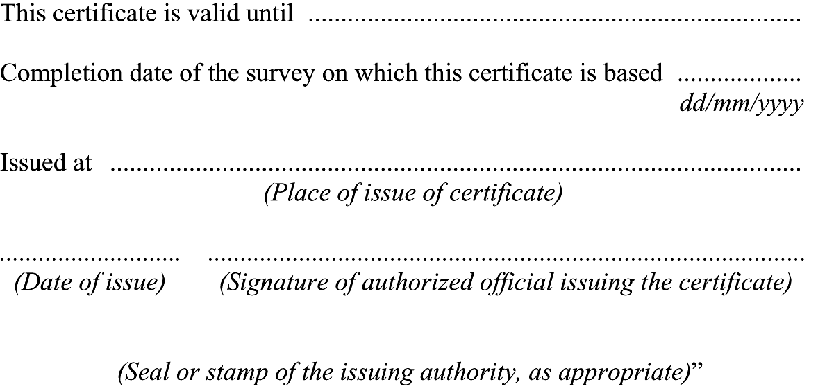
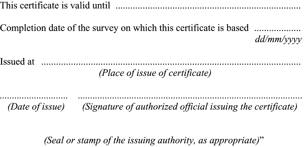
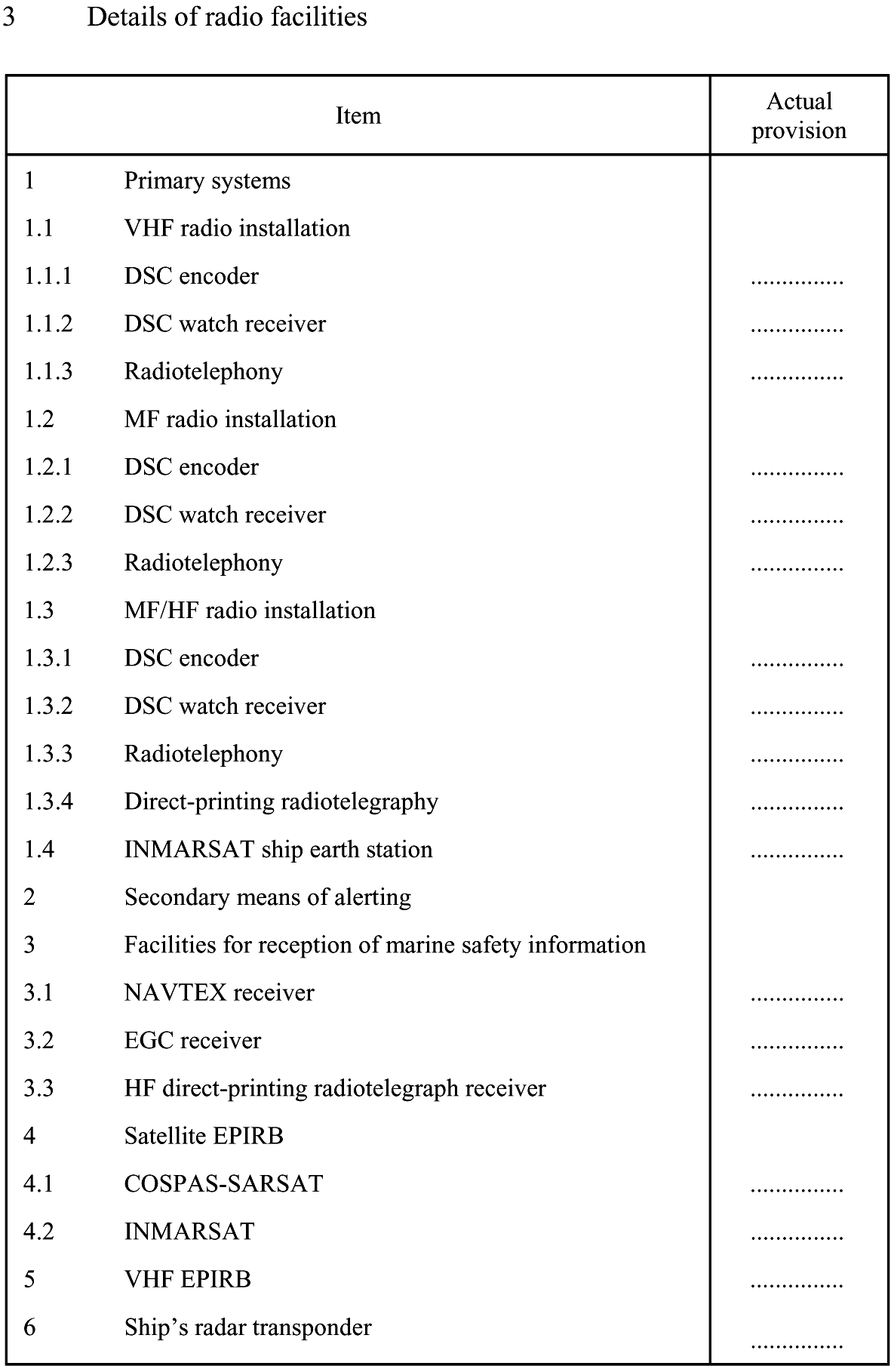
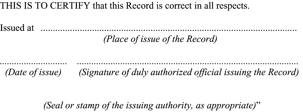
13. The following new section is inserted between the section commencing with the words “This certificate is valid until” and the section commencing with the words “Issued at”:
14. The following new section is inserted between the section commencing with the words “This certificate is valid until” and the section commencing with the words “Issued at”:

15. The following new section is inserted between the section commencing with the words “This certificate is valid until” and the section commencing with the words “Issued at”:
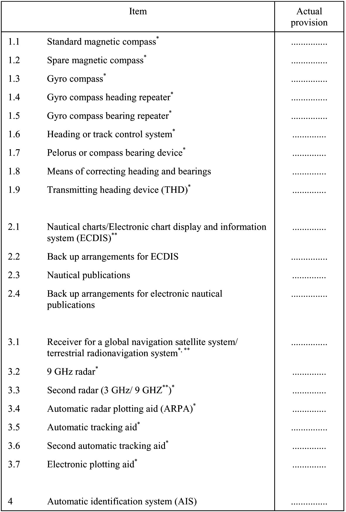
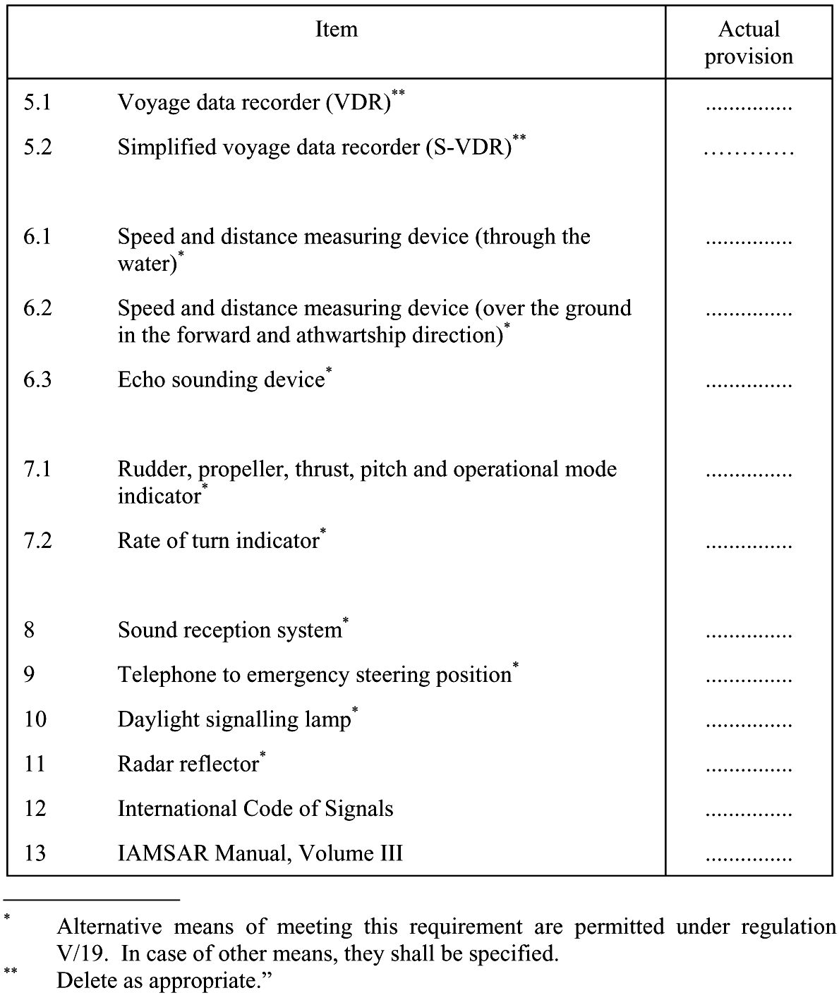
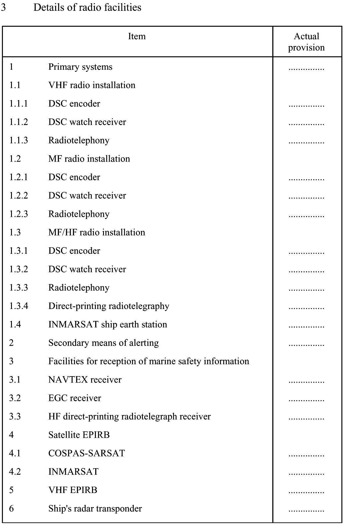
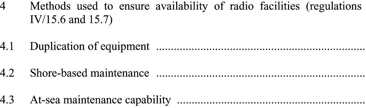
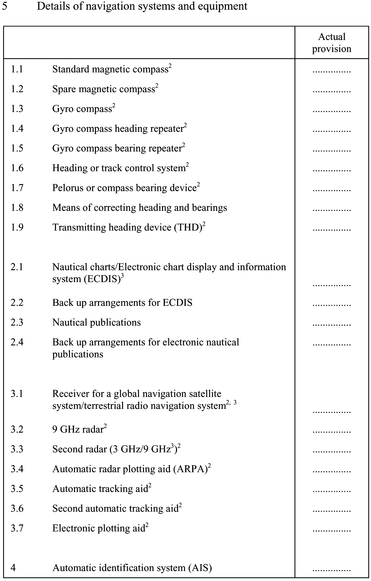
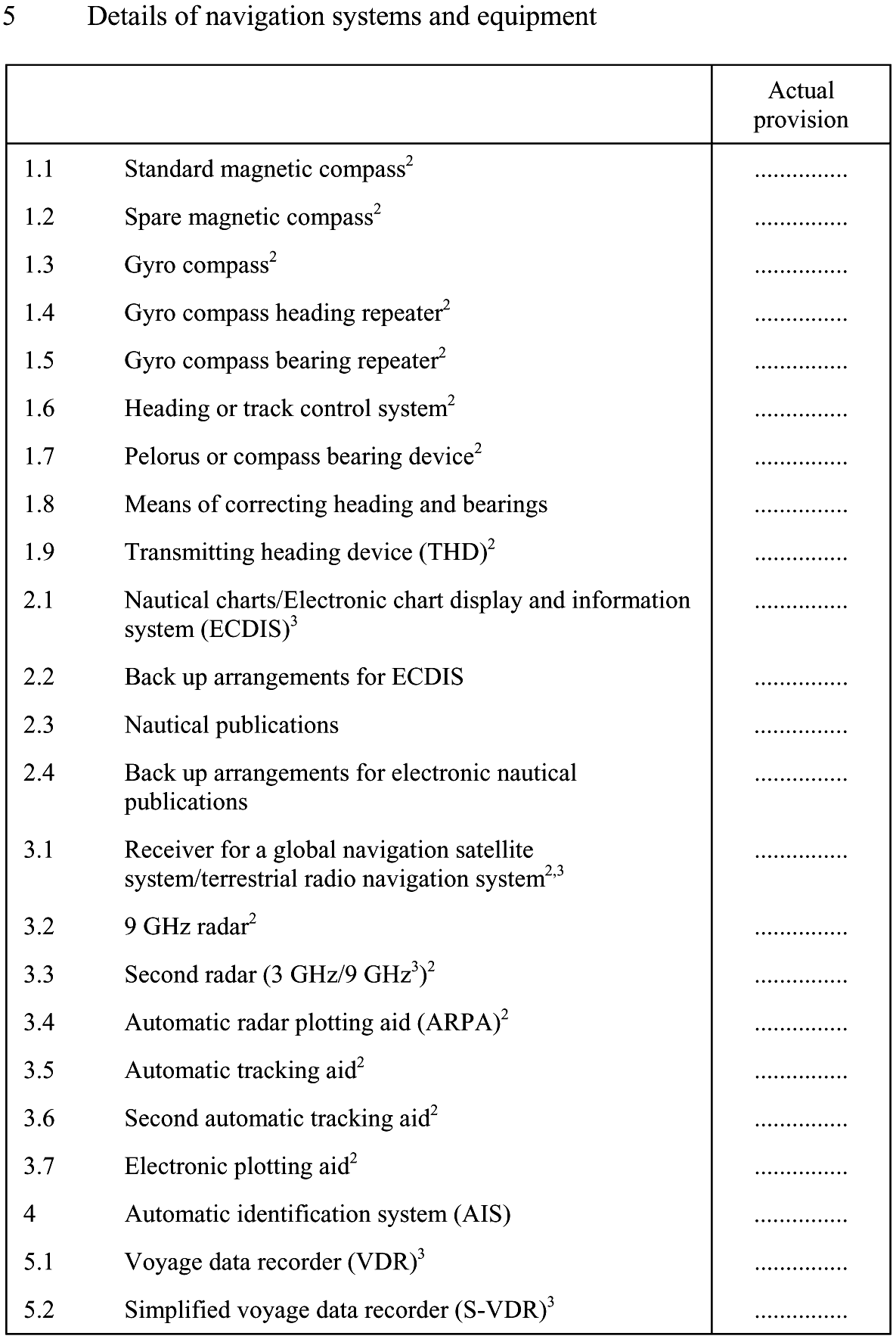
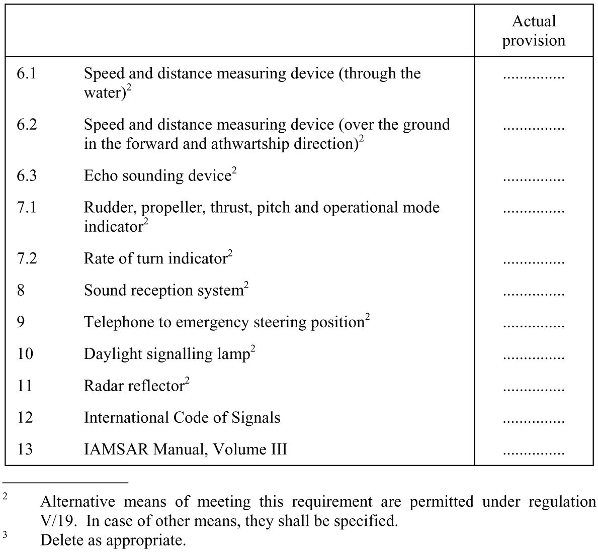
16. Existing section 3 is replaced by the following:
“3. Details of navigational systems and equipment
17. The following new section is inserted between the section commencing with the words “This certificate is valid until” and the section commencing with the words “Issued at”:

18. The existing form of the certificate is replaced by the following:
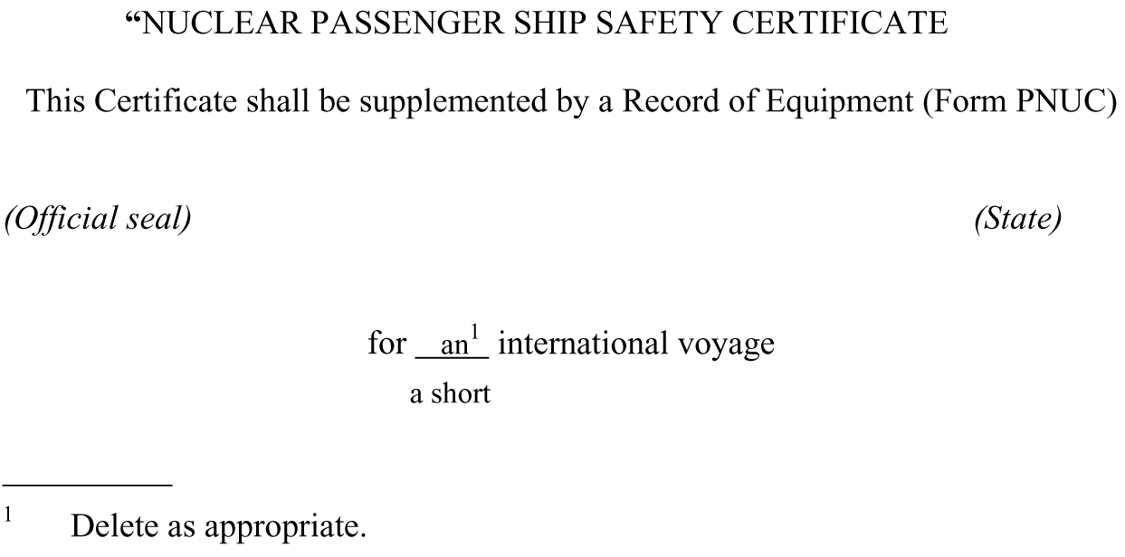
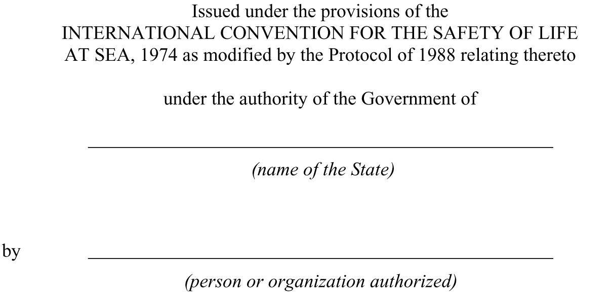
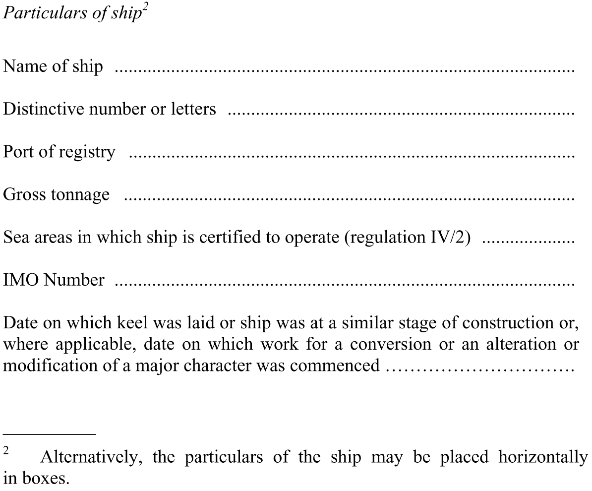
THIS IS TO CERTIFY:
1. That the ship has been surveyed in accordance with the requirements of regulation VIII/9 of the Convention.
2. That the ship, being a nuclear ship, complied with all the requirements of chapter VIII of the Convention and conformed to the Safety Assessment approved for the ship; and that:
2.1. the ship complied with the requirements of the Convention as regards:
.1. the structure, main and auxiliary machinery, boilers and other pressure vessels, including the nuclear propulsion plant and the collision protective structure;
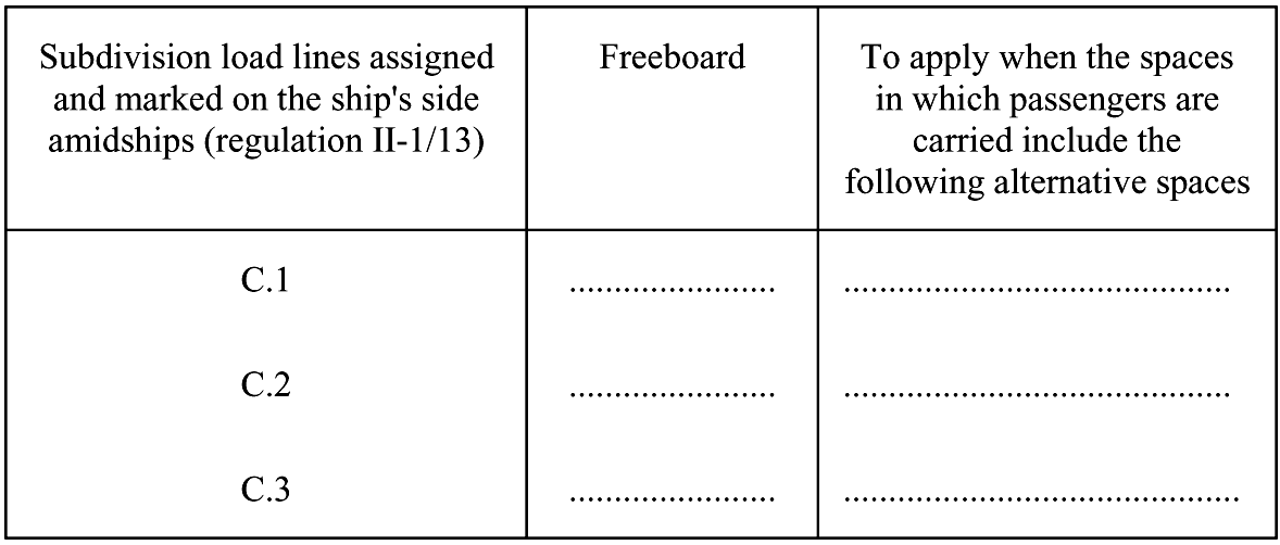
.2. the watertight subdivision arrangements and details;
.3. the following subdivision load lines:
2.2. the ship complied with the requirements of the Convention as regards structural fire protection, fire safety systems and appliances and fire control plans;
2.3. the ship complied with the requirements of the Convention as regards radiation protection systems and equipment;
2.4. the life-saving appliances and the equipment of the lifeboats, liferafts and rescue boats were provided in accordance with the requirements of the Convention;
2.5. the ship was provided with a line-throwing appliance and radio installations used in life-saving appliances in accordance with the requirements of the Convention;
2.6. the ship complied with the requirements of the Convention as regards radio installations;
2.7. the functioning of the radio installations used in life-saving appliances complied with the requirements of the Convention;
2.8. the ship complied with the requirements of the Convention as regards shipborne navigational equipment, means of embarkation for pilots and nautical publications;
2.9. the ship was provided with lights, shapes, means of making sound signals and distress signals in accordance with the requirements of the Convention and the International Regulations for Preventing Collisions at Sea in force;
2.10. in all other respects the ship complied with the relevant requirements of the Convention.
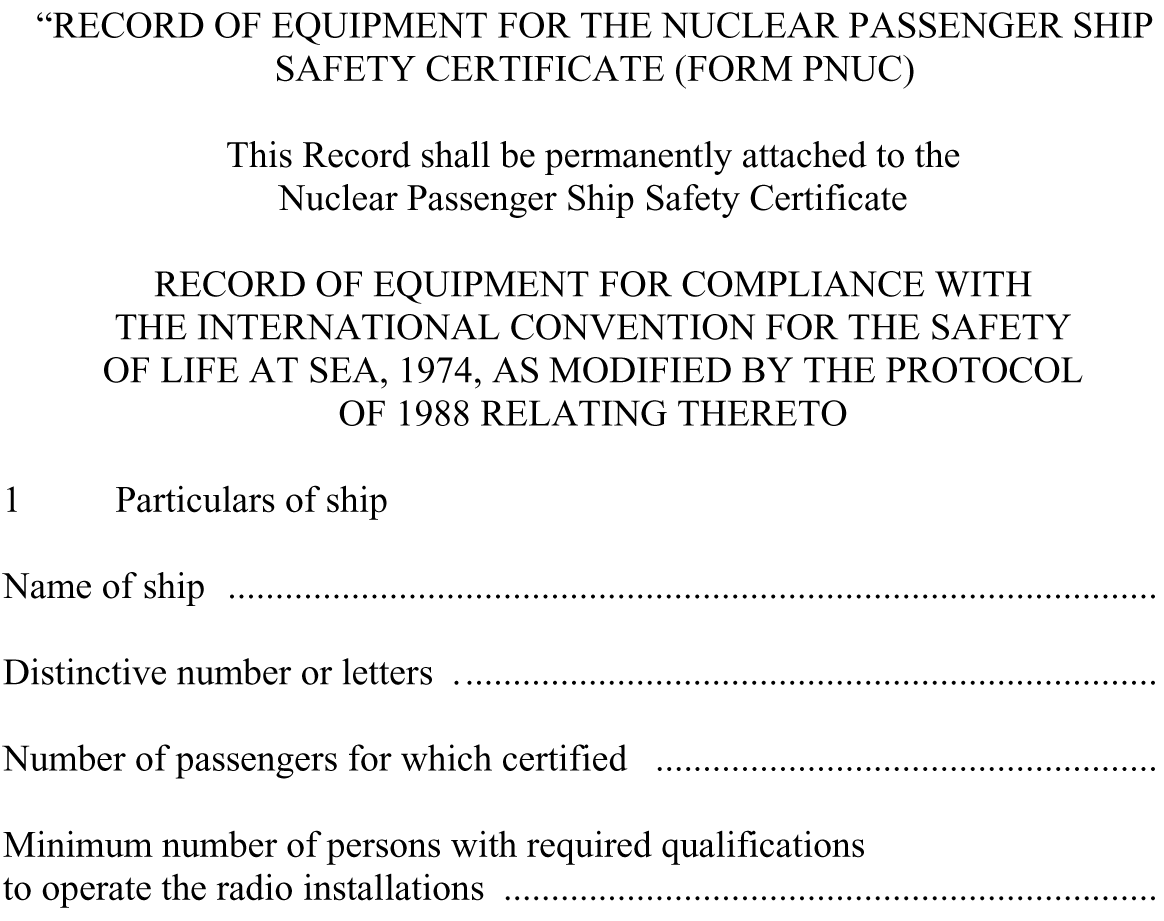
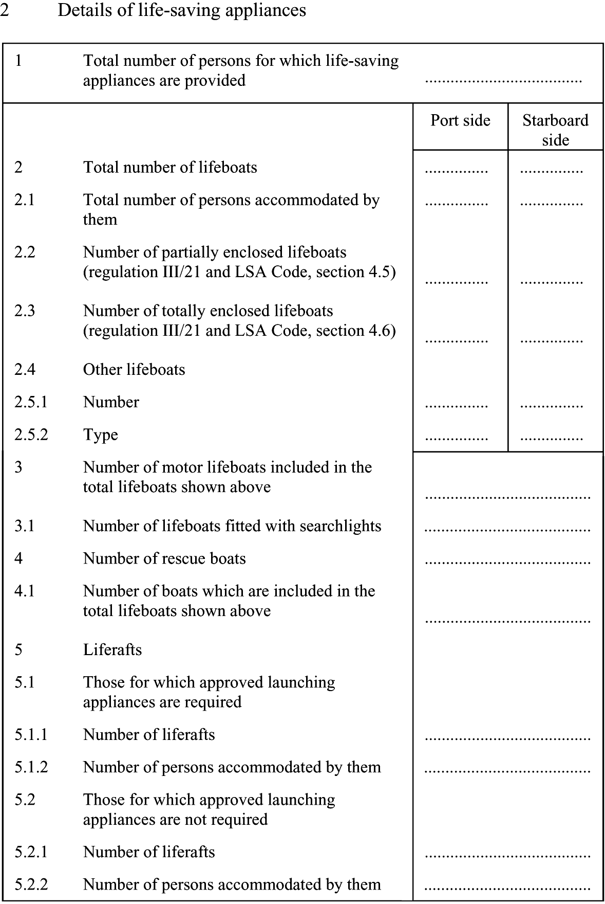
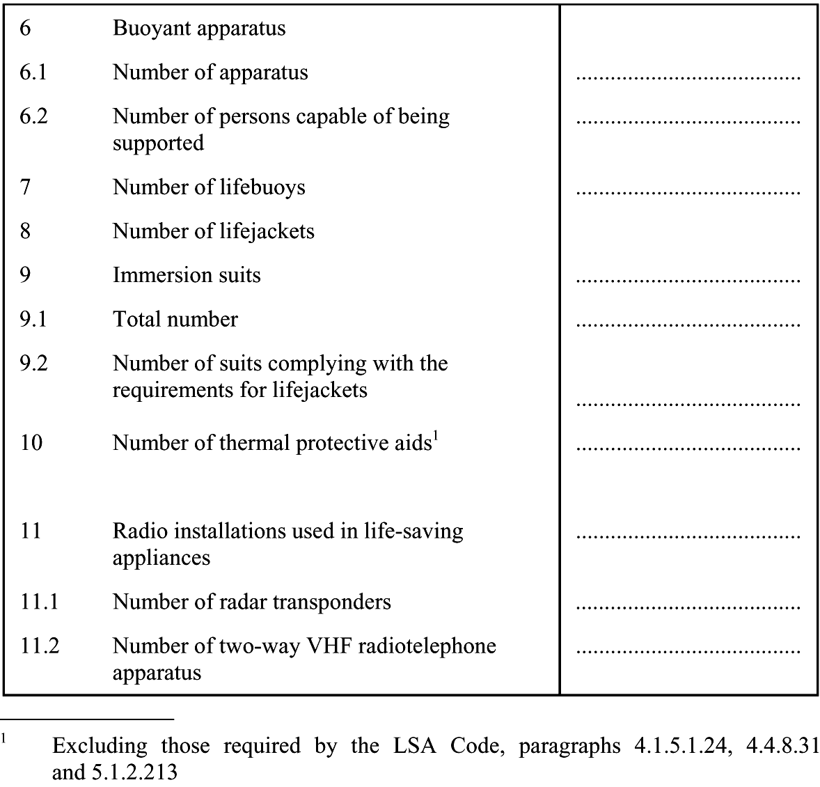
19. The following Record of Equipment for the Nuclear Passenger Ship Safety Certificate is added after the form of the Nuclear Passenger Ship Safety Certificate:
20. The existing form of the certificate is replaced by the following:
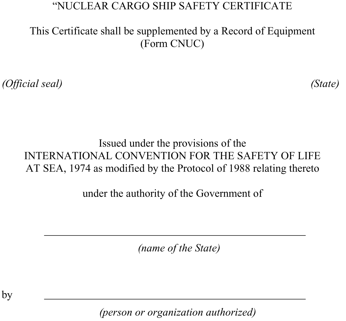
THIS IS TO CERTIFY:
1. That the ship has been surveyed in accordance with the requirements of regulation VIII/9 of the Convention.
2. That the ship, being a nuclear ship, complied with all the requirements of chapter VIII of the Convention and conformed to the Safety Assessment approved for the ship; and that:
2.1. the condition of the structure, machinery and equipment as defined in regulation I/10 (as applicable to comply with regulation VIII/9), including the nuclear propulsion plant and the collision protective structure, was satisfactory and the ship complied with the relevant requirements of chapter II-1 and chapter II-2 of the Convention (other than those relating to fire safety systems and appliances and fire control plans);
2.2. the ship complied with the requirements of the Convention as regards fire safety systems and appliances and fire control plans;
2.3. the life-saving appliances and the equipment of the lifeboats, liferafts and rescue boats were provided in accordance with the requirements of the Convention;
2.4. the ship was provided with a line-throwing appliance and radio installations used in life-saving appliances in accordance with the requirements of the Convention;
2.5. the ship complied with the requirements of the Convention as regards radio installations;
2.6. the functioning of the radio installations used in life-saving appliances complied with the requirements of the Convention;
2.7. the ship complied with the requirements of the Convention as regards shipborne navigational equipment, means of embarkation for pilots and nautical publications;
2.8. the ship was provided with lights, shapes, means of making sound signals and distress signals in accordance with the requirements of the Convention and the International Regulations for Preventing Collisions at Sea in force;
2.9. in all other respects the ship complied with the relevant requirements of the regulations, so far as these requirements apply thereto.
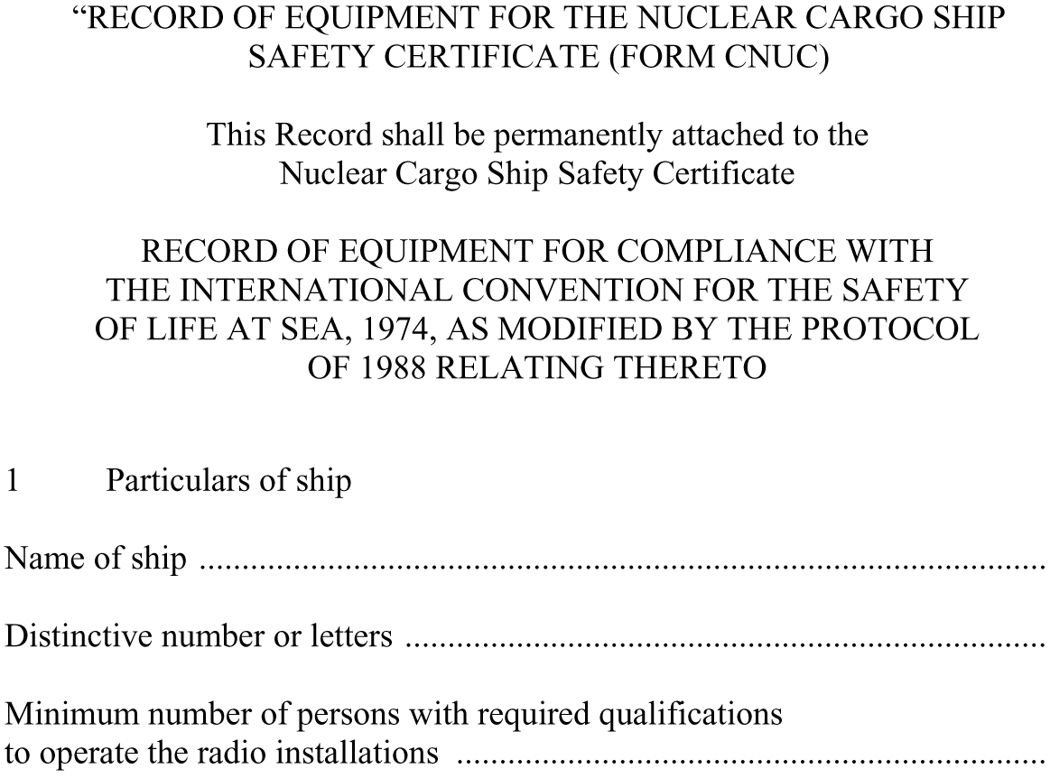
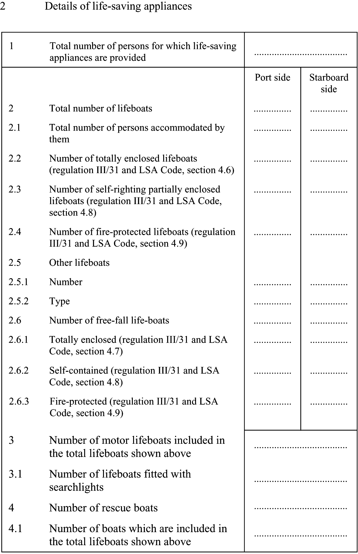
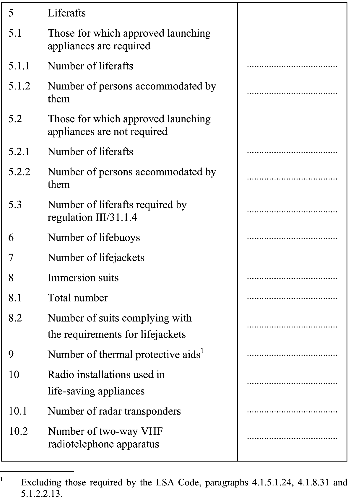
21. The following Record of Equipment for the Nuclear Cargo Ship Safety Certificate is added after the form of the Nuclear Cargo Ship Safety Certificate:

Resolutie MSC.194(80) van 20 mei 2005
Bij Resolutie MSC.194(80) heeft de Maritieme Veiligheidscommissie van de Internationale Maritieme Organisatie op 20 mei 2005 in overeenstemming met artikel VIII(b)(iv) van het Verdrag wijzigingen aangenomen. De Engelse tekst1) van de Resolutie en de wijzigingen luidt als volgt:
(adopted on 20 May 2005)
Adoption of Amendments to the International Convention for the Safety of Life at Sea, 1974, as amended
The Maritime Safety Committee,
Recalling Article 28(b) of the Convention on the International Maritime Organization concerning the functions of the Committee,
Recalling further article VIII(b) of the International Convention for the Safety of Life at Sea (SOLAS), 1974 (hereinafter referred to as .the Convention.), concerning the amendment procedure applicable to the Annex to the Convention, other than the provisions of chapter I thereof,
Having considered, at its eightieth session, amendments to the Convention, proposed and circulated in accordance with article VIII(b)(i) thereof,
1. Adopts, in accordance with article VIII(b)(iv) of the Convention, amendments to the Convention, the text of which is set out in the annexes to the present resolution;
2. Determines, in accordance with article VIII(b)(vi)(2)(bb) of the Convention, that:
a) the said amendments set out in annex 1 shall be deemed to have been accepted on 1 July 2006; and
b) the said amendments set out in annex 2 shall be deemed to have been accepted on 1 July 2008,
unless, prior to that date, more than one third of the Contracting Governments to the Convention or Contracting Governments the combined merchant fleets of which constitute not less than 50% of the gross tonnage of the world’s merchant fleet, have notified their objections to the amendments;
3. Invites SOLAS Contracting Governments to note that, in accordance with article VIII(b)(vii)(2) of the Convention:
a) the amendments set out in annex 1 shall enter into force on 1 January 2007; and
b) the amendments set out in annex 2 shall enter into force on 1 January 2009,
upon their acceptance in accordance with paragraph 2 above;
4. Requests the Secretary-General, in conformity with article VIII(b)(v) of the Convention, to transmit certified copies of the present resolution and the text of the amendments contained in the Annex to all Contracting Governments to the Convention;
5. Further requests the Secretary-General to transmit copies of this resolution and its Annex to Members of the Organization, which are not Contracting Governments to the Convention.
In addition to the requirements contained elsewhere in the present regulations, ships shall be designed, constructed and maintained in compliance with the structural, mechanical and electrical requirements of a classification society which is recognized by the Administration in accordance with the provisions of regulation XI-1/1, or with applicable national standards of the Administration which provide an equivalent level of safety.
(This regulation applies to oil tankers and bulk carriers constructed on or after 1 July 1998)
All dedicated seawater ballast tanks shall have an efficient corrosion prevention system, such as hard protective coatings or equivalent. The coatings should preferably be of a light colour. The scheme for the selection, application and maintenance of the system shall be approved by the Administration, based on the guidelines adopted by the Organization.1)
Where appropriate, sacrificial anodes shall also be used.
1. For the purpose of this regulation and regulation 3-4, tankers include oil tankers as defined in regulation 2, chemical tankers as defined in regulation VII/8.2 and gas carriers as defined in regulation VII/11.2.
2. Every tanker shall be provided with the means to enable the crew to gain safe access to the bow even in severe weather conditions. Such means of access shall be approved by the Administration based on the guidelines developed by the Organization.2)
1. Emergency towing arrangements shall be fitted at both ends on board every tanker of not less than 20,000 tonnes deadweight.
2. For tankers constructed on or after 1 July 2002:
.1. the arrangements shall, at all times, be capable of rapid deployment in the absence of main power on the ship to be towed and easy connection to the towing ship. At least one of the emergency towing arrangements shall be pre-rigged ready for rapid deployment; and
.2. emergency towing arrangements at both ends shall be of adequate strength taking into account the size and deadweight of the ship, and the expected forces during bad weather conditions. The design and construction and prototype testing of the emergency towing arrangements shall be approved by the Administration, based on the Guidelines developed by the Organization.
3. For tankers constructed before 1 July 2002, the design and construction of emergency towing arrangements shall be approved by the Administration, based on the Guidelines developed by the Organization.3)
1. This regulation shall apply to materials used for the structure, machinery, electrical installations and equipment covered by the present Convention.
2. For all ships, new installation of materials which contain asbestos shall be prohibited except for:
.1. vanes used in rotary vane compressors and rotary vane vacuum pumps;
.2. watertight joints and linings used for the circulation of fluids when, at high temperature (in excess of 350ºC) or pressure (in excess of 7 x 10⁶ Pa), there is a risk of fire, corrosion or toxicity; and
.3. supple and flexible thermal insulation assemblies used for temperatures above 1000ºC.
1. Application
1.1. Except as provided for in paragraph 1.2, this regulation applies to oil tankers of 500 gross tonnage and over and bulk carriers, as defined in regulation IX/1, of 20,000 gross tonnage and over, constructed on or after 1 January 2006.
1.2. Oil tankers of 500 gross tonnage and over constructed on or after 1 October 1994 but before 1 January 2005 shall comply with the provisions of regulation II-1/12-2 adopted by resolution MSC.27(61).
2. Means of access to cargo and other spaces
2.1. Each space shall be provided with means of access to enable, throughout the life of a ship, overall and close-up inspections and thickness measurements of the ship’s structures to be carried out by the Administration, the company, as defined in regulation IX/1, and the ship.’s personnel and others as necessary. Such means of access shall comply with the requirements of paragraph 5 and with the Technical provisions for means of access for inspections, adopted by the Maritime Safety Committee by resolution MSC.133(76), as may be amended by the Organization, provided that such amendments are adopted, brought into force and take effect in accordance with the provisions of article VIII of the present Convention concerning the amendment procedures applicable to the Annex other than chapter I.
2.2. Where a permanent means of access may be susceptible to damage during normal cargo loading and unloading operations or where it is impracticable to fit permanent means of access, the Administration may allow, in lieu thereof, the provision of movable or portable means of access, as specified in the Technical provisions, provided that the means of attaching, rigging, suspending or supporting the portable means of access forms a permanent part of the ship’s structure. All portable equipment shall be capable of being readily erected or deployed by ship’s personnel.
2.3. The construction and materials of all means of access and their attachment to the ship’s structure shall be to the satisfaction of the Administration. The means of access shall be subject to survey prior to, or in conjunction with, its use in carrying out surveys in accordance with regulation I/10.
3. Safe access to cargo holds, cargo tanks, ballast tanks and other spaces
3.1. Safe access4) to cargo holds, cofferdams, ballast tanks, cargo tanks and other spaces in the cargo area shall be direct from the open deck and such as to ensure their complete inspection. Safe access to double bottom spaces or to forward ballast tanks may be from a pump-room, deep cofferdam, pipe tunnel, cargo hold, double hull space or similar compartment not intended for the carriage of oil or hazardous cargoes.
3.2. Tanks, and subdivisions of tanks, having a length of 35 m or more, shall be fitted with at least two access hatchways and ladders, as far apart as practicable. Tanks less than 35 m in length shall be served by at least one access hatchway and ladder. When a tank is subdivided by one or more swash bulkheads or similar obstructions which do not allow ready means of access to the other parts of the tank, at least two hatchways and ladders shall be fitted.
3.3. Each cargo hold shall be provided with at least two means of access as far apart as practicable. In general, these accesses should be arranged diagonally, for example one access near the forward bulkhead on the port side, the other one near the aft bulkhead on the starboard side.
4. Ship structure access manual
4.1. A ship’s means of access to carry out overall and close-up inspections and thickness measurements shall be described in a Ship structure access manual approved by the Administration, an updated copy of which shall be kept on board. The Ship structure access manual shall include the following for each space:
.1. plans showing the means of access to the space, with appropriate technical specifications and dimensions;
.2. plans showing the means of access within each space to enable an overall inspection to be carried out, with appropriate technical specifications and dimensions. The plans shall indicate from where each area in the space can be inspected;
.3. plans showing the means of access within the space to enable close-up inspections to be carried out, with appropriate technical specifications and dimensions. The plans shall indicate the positions of critical structural areas, whether the means of access is permanent or portable and from where each area can be inspected;
.4. instructions for inspecting and maintaining the structural strength of all means of access and means of attachment, taking into account any corrosive atmosphere that may be within the space;
.5. instructions for safety guidance when rafting is used for close-up inspections and thickness measurements;
.6. instructions for the rigging and use of any portable means of access in a safe manner;
.7. an inventory of all portable means of access; and
.8. records of periodical inspections and maintenance of the ship’s means of access.
4.2. For the purpose of this regulation .critical structural areas. are locations which have been identified from calculations to require monitoring or from the service history of similar or sister ships to be sensitive to cracking, buckling, deformation or corrosion which would impair the structural integrity of the ship.
5. General technical specifications
5.1. For access through horizontal openings, hatches or manholes, the dimensions shall be sufficient to allow a person wearing a self-contained air-breathing apparatus and protective equipment to ascend or descend any ladder without obstruction and also provide a clear opening to facilitate the hoisting of an injured person from the bottom of the space. The minimum clear opening shall not be less than 600 mm x 600 mm. When access to a cargo hold is arranged through the cargo hatch, the top of the ladder shall be placed as close as possible to the hatch coaming. Access hatch coamings having a height greater than 900 mm shall also have steps on the outside in conjunction with the ladder.
5.2. For access through vertical openings, or manholes, in swash bulkheads, floors, girders and web frames providing passage through the length and breadth of the space, the minimum opening shall be not less than 600 mm x 800 mm at a height of not more than 600 mm from the bottom shell plating unless gratings or other foot holds are provided.
5.3. For oil tankers of less than 5,000 tonnes deadweight, the Administration may approve, in special circumstances, smaller dimensions for the openings referred to in paragraphs 5.1 and 5.2, if the ability to traverse such openings or to remove an injured person can be proved to the satisfaction of the Administration.
1. A set of as-built construction drawings5) and other plans showing any subsequent structural alterations shall be kept on board a ship constructed on or after 1 January 2007.
2. An additional set of such drawings shall be kept ashore by the Company, as defined in regulation IX/1.2.
1. This regulation applies to ships constructed on or after 1 January 2007, but does not apply to emergency towing arrangements provided in accordance with regulation 3-4.
2. Ships shall be provided with arrangements, equipment and fittings of sufficient safe working load to enable the safe conduct of all towing and mooring operations associated with the normal operation of the ship.
3. Arrangements, equipment and fittings provided in accordance with paragraph 2 shall meet the appropriate requirements of the Administration or an organization recognized by the Administration under regulation I/6.6)
4. Each fitting or item of equipment provided under this regulation shall be clearly marked with any restrictions associated with its safe operation, taking into account the strength of its attachment to the ship’s structure.”
3. The following new regulation 23-3 is added after existing regulation 23-2:
1. Single hold cargo ships other than bulk carriers constructed before 1 January 2007 shall comply with the requirements of this regulation not later than the date of the first intermediate or renewal survey of the ship to be carried out after 1 January 2007, whichever comes first.
2. For the purpose of this regulation, freeboard deck has the meaning defined in the International Convention on Load Lines in force.
3. Ships having a length (L) of less than 80 m, or 100 m if constructed before 1 July 1998, and a single cargo hold below the freeboard deck or cargo holds below the freeboard deck which are not separated by at least one bulkhead made watertight up to that deck, shall be fitted in such space or spaces with water level detectors7) .
4. The water level detectors required by paragraph 3 shall:
.1. give an audible and visual alarm at the navigation bridge when the water level above the inner bottom in the cargo hold reaches a height of not less than 0.3 m, and another when such level reaches not more than 15% of the mean depth of the cargo hold; and
.2. be fitted at the aft end of the hold, or above its lowest part where the inner bottom is not parallel to the designed waterline. Where webs or partial watertight bulkheads are fitted above the inner bottom, Administrations may require the fitting of additional detectors.
5. The water level detectors required by paragraph 3 need not be fitted in ships complying with regulation XII/12, or in ships having watertight side compartments each side of the cargo hold length extending vertically at least from inner bottom to freeboard deck.”
1. The existing paragraph 2.10 is deleted.
2. The following new paragraph 6 is added after the existing paragraph 5:
“6. Ships constructed on or after 1 July 2004 shall comply with the requirements of paragraphs 1 to 5, as amended, as follows:
.1. a new subparagraph .10 is added to paragraph 2 to read as follows:
“.10. automation systems shall be designed in a manner which ensures that threshold warning of impending or imminent slowdown or shutdown of the propulsion system is given to the officer in charge of the navigational watch in time to assess navigational circumstances in an emergency. In particular, the systems shall control, monitor, report, alert and take safety action to slow down or stop propulsion while providing the officer in charge of the navigational watch an opportunity to manually intervene, except for those cases where manual intervention will result in total failure of the engine and/or propulsion equipment within a short time, for example in the case of overspeed.””
1. The existing text of parts A, B and B-1 of the chapter is replaced by the following:
1.1. Unless expressly provided otherwise, this chapter shall apply to ships the keels of which are laid or which are at a similar stage of construction on or after 1 January 2009.
1.2. For the purpose of this chapter, the term a similar stage of construction means the stage at which:
.1. construction identifiable with a specific ship begins; and
.2. assembly of that ship has commenced comprising at least 50 tonnes or one per cent of the estimated mass of all structural material, whichever is less.
1.3. For the purpose of this chapter:
.1. the expression ships constructed means ships the keels of which are laid or which are at a similar stage of construction;
.2. the expression all ships means ships constructed before, on or after 1 January 2009;
.3. a cargo ship, whenever built, which is converted to a passenger ship shall be treated as a passenger ship constructed on the date on which such a conversion commences;
.4. the expression alterations and modifications of a major character means, in the context of cargo ship subdivision and stability, any modification to the construction which affects the level of subdivision of that ship. Where a cargo ship is subject to such modification, it shall be demonstrated that the A/R ratio calculated for the ship after such modifications is not less than the A/R ratio calculated for the ship before the modification.
However, in those cases where the ship’s A/R ratio before modification is equal to or greater than unity, it is only necessary that the ship after modification has an A value which is not less than R, calculated for the modified ship.
2. Unless expressly provided otherwise, for ships constructed before 1 January 2009, the Administration shall ensure that the requirements which are applicable under chapter II-1 of the International Convention for the Safety of Life at Sea, 1974, as amended by resolutions MSC.1(XLV), MSC.6(48), MSC.11(55), MSC.12(56), MSC.13(57), MSC.19(58), MSC.26(60), MSC.27(61), Resolution 1 of the 1995 SOLAS Conference, MSC.47(66), MSC.57(67), MSC.65(68), MSC.69(69), MSC.99(73), MSC.134(76), MSC.151(78) and MSC.170(79) are complied with.
3. All ships which undergo repairs, alterations, modifications and outfitting related thereto shall continue to comply with at least the requirements previously applicable to these ships. Such ships, if constructed before the date on which any relevant amendments enter into force, shall, as a rule, comply with the requirements for ships constructed on or after that date to at least the same extent as they did before undergoing such repairs, alterations, modifications or outfitting. Repairs, alterations and modifications of a major character and outfitting related thereto shall meet the requirements for ships constructed on or after the date on which any relevant amendments enter into force, in so far as the Administration deems reasonable and practicable.
4. The Administration of a State may, if it considers that the sheltered nature and conditions of the voyage are such as to render the application of any specific requirements of this chapter unreasonable or unnecessary, exempt from those requirements individual ships or classes of ships entitled to fly the flag of that State which, in the course of their voyage, do not proceed more than 20 miles from the nearest land.
5. In the case of passenger ships which are employed in special trades for the carriage of large numbers of special trade passengers, such as the pilgrim trade, the Administration of the State whose flag such ships are entitled to fly, if satisfied that it is impracticable to enforce compliance with the requirements of this chapter, may exempt such ships from those requirements, provided that they comply fully with the provisions of:
.1. the rules annexed to the Special Trade Passenger Ships Agreement, 1971; and
.2. the rules annexed to the Protocol on Space Requirements for Special Trade Passenger Ships, 1973.
For the purpose of this chapter, unless expressly provided otherwise:
1. Subdivision length (Ls) of the ship is the greatest projected moulded length of that part of the ship at or below deck or decks limiting the vertical extent of flooding with the ship at the deepest subdivision draught.
2. Mid-length is the mid-point of the subdivision length of the ship.
3. Aft terminal is the aft limit of the subdivision length.
4. Forward terminal is the forward limit of the subdivision length.
5. Length (L) is the length as defined in the International Convention on Load Lines in force.
6. Freeboard deck is the deck as defined in the International Convention on Load Lines in force.
7. Forward perpendicular is the forward perpendicular as defined in the International Convention on Load Lines in force.
8. Breadth (B) is the greatest moulded breadth of the ship at or below the deepest subdivision draught.
9. Draught (d) is the vertical distance from the keel line at mid-length to the waterline in question.
10. Deepest subdivision draught (ds) is the waterline which corresponds to the summer load line draught of the ship.
11. Light service draught (dl) is the service draught corresponding to the lightest anticipated loading and associated tankage, including, however, such ballast as may be necessary for stability and/or immersion. Passenger ships should include the full complement of passengers and crew on board.
12. Partial subdivision draught (dp) is the light service draught plus 60% of the difference between the light service draught and the deepest subdivision draught.
13. Trim is the difference between the draught forward and the draught aft, where the draughts are measured at the forward and aft terminals respectively, disregarding any rake of keel.
14. Permeability (μ) of a space is the proportion of the immersed volume of that space which can be occupied by water.
15. Machinery spaces are spaces between the watertight boundaries of a space containing the main and auxiliary propulsion machinery, including boilers, generators and electric motors primarily intended for propulsion. In the case of unusual arrangements, the Administration may define the limits of the machinery spaces.
16. Weathertight means that in any sea conditions water will not penetrate into the ship.
17. Watertight means having scantlings and arrangements capable of preventing the passage of water in any direction under the head of water likely to occur in intact and damaged conditions. In the damaged condition, the head of water is to be considered in the worst situation at equilibrium, including intermediate stages of flooding.
18. Design pressure means the hydrostatic pressure for which each structure or appliance assumed watertight in the intact and damage stability calculations is designed to withstand.
19. Bulkhead deck in a passenger ship means the uppermost deck at any point in the subdivision length (Ls ) to which the main bulkheads and the ship’s shell are carried watertight and the lowermost deck from which passenger and crew evacuation will not be impeded by water in any stage of flooding for damage cases defined in regulation 8 and in part B-2 of this chapter. The bulkhead deck may be a stepped deck. In a cargo ship the freeboard deck may be taken as the bulkhead deck.
20. Deadweight is the difference in tonnes between the displacement of a ship in water of a specific gravity of 1.025 at the draught corresponding to the assigned summer freeboard and the lightweight of the ship.
21. Lightweight is the displacement of a ship in tonnes without cargo, fuel, lubricating oil, ballast water, fresh water and feedwater in tanks, consumable stores, and passengers and crew and their effects.
22. Oil tanker is the oil tanker defined in regulation 1 of Annex 1 of the Protocol of 1978 relating to the International Convention for the Prevention of Pollution from Ships, 1973.
23. Ro-ro passenger ship means a passenger ship with ro-ro spaces or special category spaces as defined in regulation II-2/3.
24. Bulk carrier means a bulk carrier as defined in regulation XII/1.1.
25. Keel line is a line parallel to the slope of the keel passing amidships through:
.1. the top of the keel at centreline or line of intersection of the inside of shell plating with the keel if a bar keel extends below that line, on a ship with a metal shell; or
.2. in wood and composite ships, the distance is measured from the lower edge of the keel rabbet. When the form at the lower part of the midship section is of a hollow character, or where thick garboards are fitted, the distance is measured from the point where the line of the flat of the bottom continued inward intersects the centreline amidships.
26. Amidship is at the middle of the length (L).
For the purpose of parts C, D and E, unless expressly provided otherwise:
1. Steering gear control system is the equipment by which orders are transmitted from the navigating bridge to the steering gear power units. Steering gear control systems comprise transmitters, receivers, hydraulic control pumps and their associated motors, motor controllers, piping and cables.
2. Main steering gear is the machinery, rudder actuators, steering gear, power units, if any, and ancillary equipment and the means of applying torque to the rudder stock (e.g. tiller or quadrant) necessary for effecting movement of the rudder for the purpose of steering the ship under normal service conditions.
3. Steering gear power unit is:
.1. in the case of electric steering gear, an electric motor and its associated electrical equipment;
.2. in the case of electrohydraulic steering gear, an electric motor and its associated electrical equipment and connected pump; or
.3. in the case of other hydraulic steering gear, a driving engine and connected pump.
4. Auxiliary steering gear is the equipment other than any part of the main steering gear necessary to steer the ship in the event of failure of the main steering gear but not including the tiller, quadrant or components serving the same purpose.
5. Normal operational and habitable condition is a condition under which the ship as a whole, the machinery, services, means and aids ensuring propulsion, ability to steer, safe navigation, fire and flooding safety, internal and external communications and signals, means of escape, and emergency boat winches, as well as the designed comfortable conditions of habitability are in working order and functioning normally.
6. Emergency condition is a condition under which any services needed for normal operational and habitable conditions are not in working order due to failure of the main source of electrical power.
7. Main source of electrical power is a source intended to supply electrical power to the main switchboard for distribution to all services necessary for maintaining the ship in normal operational and habitable conditions.
8. Dead ship condition is the condition under which the main propulsion plant, boilers and auxiliaries are not in operation due to the absence of power.
9. Main generating station is the space in which the main source of electrical power is situated.
10. Main switchboard is a switchboard which is directly supplied by the main source of electrical power and is intended to distribute electrical energy to the ship’s services.
11. Emergency switchboard is a switchboard which in the event of failure of the main electrical power supply system is directly supplied by the emergency source of electrical power or the transitional source of emergency power and is intended to distribute electrical energy to the emergency services.
12. Emergency source of electrical power is a source of electrical power, intended to supply the emergency switchboard in the event of a failure of the supply from the main source of electrical power.
13. Power actuating system is the hydraulic equipment provided for supplying power to turn the rudder stock, comprising a steering gear power unit or units, together with the associated pipes and fittings, and a rudder actuator. The power actuating systems may share common mechanical components (i.e. tiller, quadrant and rudder stock) or components serving the same purpose.
14. Maximum ahead service speed is the greatest speed which the ship is designed to maintain in service at sea at the deepest sea-going draught.
15. Maximum astern speed is the speed which it is estimated the ship can attain at the designed maximum astern power at the deepest sea-going draught.
16. Machinery spaces are all machinery spaces of category A and all other spaces containing propelling machinery, boilers, oil fuel units, steam and internal combustion engines, generators and major electrical machinery, oil filling stations, refrigerating, stabilizing, ventilation and air conditioning machinery, and similar spaces, and trunks to such spaces.
17. Machinery spaces of category A are those spaces and trunks to such spaces which contain:
.1. internal combustion machinery used for main propulsion;
.2. internal combustion machinery used for purposes other than main propulsion where such machinery has in the aggregate a total power output of not less than 375 kW; or
.3. any oil-fired boiler or oil fuel unit.
18. Control stations are those spaces in which the ship’s radio or main navigating equipment or the emergency source of power is located or where the fire recording or fire control equipment is centralized.
19. Chemical tanker is a cargo ship constructed or adapted and used for the carriage in bulk of any liquid product listed in either:
.1. chapter 17 of the International Code for the Construction and Equipment of Ships Carrying Dangerous Chemicals in Bulk adopted by the Maritime Safety Committee by resolution MSC.4(48), hereinafter referred to as “the International Bulk Chemical Code”, as may be amended by the Organization; or
.2. chapter VI of the Code for the Construction and Equipment of Ships Carrying Dangerous Chemicals in Bulk adopted by the Assembly of the Organization by resolution A.212(VII), hereinafter referred to as “the Bulk Chemical Code”, as has been or may be amended by the Organization,
whichever is applicable.
20. Gas carrier is a cargo ship constructed or adapted and used for the carriage in bulk of any liquefied gas or other products listed in either:
.1. chapter 19 of the International Code for the Construction and Equipment of Ships Carrying Liquefied Gases in Bulk adopted by the Maritime Safety Committee by resolution MSC.5(48), hereinafter referred to as the “International Gas Carrier Code”, as may be amended by the Organization;
or
.2. chapter XIX of the Code for the Construction and Equipment of Ships Carrying Liquefied Gases in Bulk adopted by the Organization by resolution A.328(IX), hereinafter referred to as “the Gas Carrier Code”, as has been or may be amended by the Organization,
whichever is applicable.
1. The damage stability requirements in Parts B-1 through B-4 shall apply to cargo ships of 80 m in length (L) and upwards and to all passenger ships regardless of length but shall exclude those cargo ships which are shown to comply with subdivision and damage stability regulations in other instruments1) developed by the Organization.
2. The Administration may, for a particular ship or group of ships, accept alternative methodologies if it is satisfied that at least the same degree of safety as represented by these regulations is achieved. Any Administration which allows such alternative methodologies shall communicate to the Organization particulars thereof.
3. Ships shall be as efficiently subdivided as is possible having regard to the nature of the service for which they are intended. The degree of subdivision shall vary with the subdivision length (Ls ) of the ship and with the service, in such manner that the highest degree of subdivision corresponds with the ships of greatest subdivision length (Ls ), primarily engaged in the carriage of passengers.
4. Where it is proposed to fit decks, inner skins or longitudinal bulkheads of sufficient tightness to seriously restrict the flow of water, the Administration shall be satisfied that proper consideration is given to beneficial or adverse effects of such structures in the calculations.
1. Every passenger ship regardless of size and every cargo ship having a length (L) of 24 m and upwards, shall be inclined upon its completion and the elements of its stability determined.
2. The Administration may allow the inclining test of an individual cargo ship to be dispensed with provided basic stability data are available from the inclining test of a sister ship and it is shown to the satisfaction of the Administration that reliable stability information for the exempted ship can be obtained from such basic data, as required by regulation 5-1. A weight survey shall be carried out upon completion and the ship shall be inclined whenever in comparison with the data derived from the sister ship, a deviation from the lightship displacement exceeding 1% for ships of 160 m or more in length and 2% for ships of 50 m or less in length and as determined by linear interpolation for intermediate lengths or a deviation from the lightship longitudinal centre of gravity exceeding 0.5% of Ls is found.
3. The Administration may also allow the inclining test of an individual ship or class of ships especially designed for the carriage of liquids or ore in bulk to be dispensed with when reference to existing data for similar ships clearly indicates that due to the ship’s proportions and arrangements more than sufficient metacentric height will be available in all probable loading conditions.
4. Where any alterations are made to a ship so as to materially affect the stability information supplied to the master, amended stability information shall be provided. If necessary the ship shall be re-inclined. The ship shall be re-inclined if anticipated deviations exceed one of the values specified in paragraph 5.
5. At periodical intervals not exceeding five years, a lightweight survey shall be carried out on all passenger ships to verify any changes in lightship displacement and longitudinal centre of gravity. The ship shall be re-inclined whenever, in comparison with the approved stability information, a deviation from the lightship displacement exceeding 2% or a deviation of the longitudinal centre of gravity exceeding 1% of Ls is found or anticipated.
6. Every ship shall have scales of draughts marked clearly at the bow and stern. In the case where the draught marks are not located where they are easily readable, or operational constraints for a particular trade make it difficult to read the draught marks, then the ship shall also be fitted with a reliable draught indicating system by which the bow and stern draughts can be determined.
1. The master shall be supplied with such information satisfactory to the Administration as is necessary to enable him by rapid and simple processes to obtain accurate guidance as to the stability of the ship under varying conditions of service.
A copy of the stability information shall be furnished to the Administration.
2. The information should include:
.1. curves or tables of minimum operational metacentric height (GM) versus draught which assures compliance with the relevant intact and damage stability requirements, alternatively corresponding curves or tables of the maximum allowable vertical centre of gravity (KG) versus draught, or with the equivalents of either of these curves;
.2. instructions concerning the operation of cross-flooding arrangements; and
.3. all other data and aids which might be necessary to maintain the required intact stability and stability after damage.
3. The stability information shall show the influence of various trims in cases where the operational trim range exceeds +/- 0.5% of Ls .
4. For ships which have to fulfil the stability requirements of part B-1, information referred to in paragraph 2 are determined from considerations related to the subdivision index, in the following manner: Minimum required GM (or maximum permissible vertical position of centre of gravity KG) for the three draughts ds , dp and dl are equal to the GM (or KG values) of corresponding loading cases used for the calculation of survival factor si . For intermediate draughts, values to be used shall be obtained by linear interpolation applied to the GM value only between the deepest subdivision draught and the partial subdivision draught and between the partial load line and the light service draught respectively. Intact stability criteria will also be taken into account by retaining for each draft the maximum among minimum required GM values or the minimum of maximum permissible KG values for both criteria. If the subdivision index is calculated for different trims, several required GM curves will be established in the same way.
5. When curves or tables of minimum operational metacentric height (GM) versus draught are not appropriate, the master should ensure that the operating condition does not deviate from a studied loading condition, or verify by calculation that the stability criteria are satisfied for this loading condition.
1. The subdivision of a ship is considered sufficient if the attained subdivision index A, determined in accordance with regulation 7, is not less than the required subdivision index R calculated in accordance with this regulation and if, in addition, the partial indices As, Ap and Al are not less than 0.9R for passenger ships and 0.5R for cargo ships.
2. For all ships to which the damage stability requirements of this chapter apply, the degree of subdivision to be provided shall be determined by the required subdivision index R, as follows:
.1. In the case of cargo ships greater than 100 m in length (Ls ):
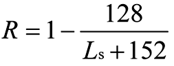
.2. In the case of cargo ships not less than 80 m in length (Ls ) and not greater than 100 m in length (Ls):
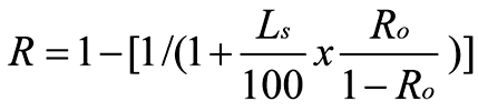
Where Ro is the value R as calculated in accordance with the formula in subparagraph .1.
.3. In the case of passenger ships:
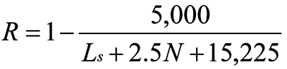
where:
N = N1 + 2N2
N1 = number of persons for whom lifeboats are provided
N2 = number of persons (including officers and crew) the ship is permitted to carry in excess of N1.
.4. Where the conditions of service are such that compliance with paragraph 2.3 of this regulation on the basis of N = N1 + 2N2 is impracticable and where the Administration considers that a suitably reduced degree of hazard exists, a lesser value of N may be taken but in no case less than N = N1 + N2.
1. The attained subdivision index A is obtained by the summation of the partial indices As, Ap and Al, (weighted as shown) calculated for the draughts ds, dp and dl defined in regulation 2 in accordance with the following formula:
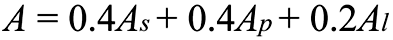
Each partial index is a summation of contributions from all damage cases taken inconsideration, using the following formula:
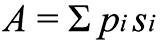
where:
i represents each compartment or group of compartments under consideration,
pi accounts for the probability that only the compartment or group of compartments under consideration may be flooded, disregarding any horizontal subdivision, as defined in regulation 7-1,
si accounts for the probability of survival after flooding the compartment or group of compartments under consideration, and includes the effect of any horizontal subdivision, as defined in regulation 7-2.
2. In the calculation of A, the level trim shall be used for the deepest subdivision draught and the partial subdivision draught. The actual service trim shall be used for the light service draught. If in any service condition, the trim variation in comparison with the calculated trim is greater than 0.5% of Ls, one or more additional calculations of A are to be submitted for the same draughts but different trims so that, for all service conditions, the difference in trim in comparison with the reference trim used for one calculation will be less than 0.5% of Ls.
3. When determining the positive righting lever (GZ) of the residual stability curve, the displacement used should be that of the intact condition. That is, the constant displacement method of calculation should be used.
4. The summation indicated by the above formula shall be taken over the ship’s subdivision length (Ls) for all cases of flooding in which a single compartment or two or more adjacent compartments are involved. In the case of unsymmetrical arrangements, the calculated A value should be the mean value obtained from calculations involving both sides. Alternatively, it should be taken as that corresponding to the side which evidently gives the least favourable result.
5. Wherever wing compartments are fitted, contribution to the summation indicated by the formula shall be taken for all cases of flooding in which wing compartments are involved. Additionally, cases of simultaneous flooding of a wing compartment or group of compartments and the adjacent inboard compartment or group of compartments, but excluding damage of transverse extent greater than one half of the ship breadth B, may be added. For the purpose of this regulation, transverse extent is measured inboard from ship’s side, at right angle to the centreline at the level of the deepest subdivision draught.
6. In the flooding calculations carried out according to the regulations, only one breach of the hull and only one free surface need to be assumed. The assumed vertical extent of damage is to extend from the baseline upwards to any watertight horizontal subdivision above the waterline or higher. However, if a lesser extent of damage will give a more severe result, such extent is to be assumed.
7. If pipes, ducts or tunnels are situated within the assumed extent of damage, arrangements are to be made to ensure that progressive flooding cannot thereby extend to compartments other than those assumed flooded. However, the Administration may permit minor progressive flooding if it is demonstrated that its effects can be easily controlled and the safety of the ship is not impaired.
1. The factor pi for a compartment or group of compartments shall be calculated in accordance with paragraphs 1.1 and 1.2 using the following notations:
j = the aftmost damage zone number involved in the damage starting with no.1 at the stern;
n = the number of adjacent damage zones involved in the damage;
k = is the number of a particular longitudinal bulkhead as barrier for transverse penetration in a damage zone counted from shell towards the centre line. The shell has k = 0;
x1 = the distance from the aft terminal of Ls to the aft end of the zone in question;
x2 = the distance from the aft terminal of Ls to the forward end of the zone in question;
b = the mean transverse distance in metres measured at right angles to the centreline at the deepest subdivision loadline between the shell and an assumed vertical plane extended between the longitudinal limits used in calculating the factor pi and which is a tangent to, or common with, all or part of the outermost portion of the longitudinal bulkhead under consideration. This vertical plane shall be so orientated that the mean transverse distance to the shell is a maximum, but not more than twice the least distance between the plane and the shell. If the upper part of a longitudinal bulkhead is below the deepest subdivision loadline the vertical plane used for determination of b is assumed to extend upwards to the deepest subdivision waterline. In any case, b is not to be taken greater than B/2.
If the damage involves a single zone only:

If the damage involves two adjacent zones:
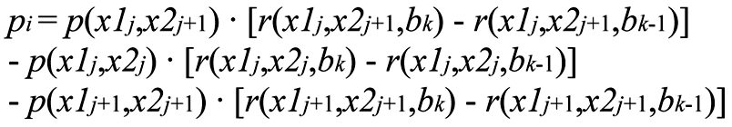
If the damage involves three or more adjacent zones:

and where r(x1, x2, b0) = 0
1.1 The factor p(x1, x2) is to be calculated according to the following formulae:
Overall normalized max damage length: | Jmax = 10/33 |
Knuckle point in the distribution: | Jkn = 5/33 |
Cumulative probability at Jkn : | pk = 11/12 |
Maximum absolute damage length: | lmax = 60 m |
Length where normalized distribution ends: | L* = 260 m |
Probability density at J = 0: |
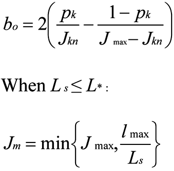
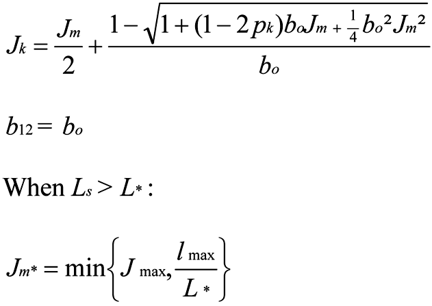
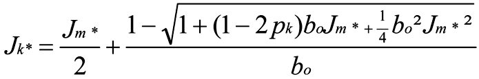
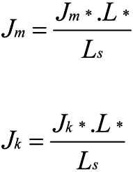
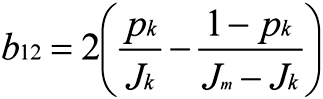
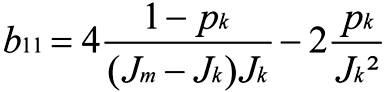
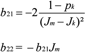
The non-dimensional damage length:
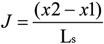
The normalized length of a compartment or group of compartments:
Jn is to be taken as the lesser of J and Jm
1.1.1. Where neither limits of the compartment or group of compartments under consideration coincides with the aft or forward terminals:
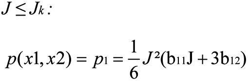
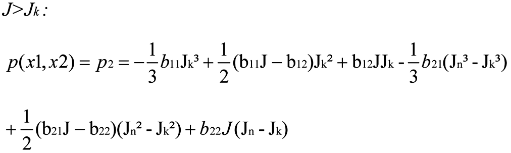
1.1.2. Where the aft limit of the compartment or group of compartments under consideration coincides with the aft terminal or the forward limit of the compartment or group of compartments under consideration coincides with the forward terminal:

1.1.3. Where the compartment or groups of compartments considered extends over the entire subdivision length (Ls ):
1.2. The factor r(x1, x2, b) shall be determined by the following formulae:

where:

1.2.1. Where the compartment or groups of compartments considered extends over the entire subdivision length (Ls ):
1.2.2. Where neither limits of the compartment or group of compartments under consideration coincides with the aft or forward terminals:
1.2.3. Where the aft limit of the compartment or group of compartments under consideration coincides with the aft terminal or the forward limit of the compartment or group of compartments under consideration coincides with the forward terminal:
1. The factor si shall be determined for each case of assumed flooding, involving a compartment or group of compartments, in accordance with the following notations and the provisions in this regulation.
Θ is the equilibrium heel angle in any stage of flooding, in degrees;
Θ is the angle, in any stage of flooding, where the righting lever becomes negative, or the angle at which an opening incapable of being closed weathertight becomes submerged;
GZmax is the maximum positive righting lever, in metres, up to the angle θv;
Range is the range of positive righting levers, in degrees, measured from the angle θe. The positive range is to be taken up to the angle θv;
Flooding stage is any discrete step during the flooding process, including the stage before equalization (if any) until final equilibrium has been reached.
1.1. The factor si , for any damage case at any initial loading condition, di , shall be obtained from the formula:
si = minimum { sintermediate,i or sfinal,i · smom,i }
where:
sintermediate,i is the probability to survive all intermediate flooding stages until the final equilibrium stage, and is calculated in accordance with paragraph 2;
sfinal,i is the probability to survive in the final equilibrium stage of flooding. It is calculated in accordance with paragraph 3;
smom,i is the probability to survive heeling moments, and is calculated in accordance with paragraph 4.
2. The factor sintermediate,i is applicable only to passenger ships (for cargo ships sintermediate,i should be taken as unity) and shall be taken as the least of the s-factors obtained from all flooding stages including the stage before equalization, if any, and is to be calculated as follows:

where GZmax is not to be taken as more than 0.05 m and Range as not more than 7°.
sintermediate = 0, if the intermediate heel angle exceeds 15º. Where cross-flooding fittings are required, the time for equalization shall not exceed 10 min.
3. The factor sfinal,i shall be obtained from the formula:
where:
GZmax is not to be taken as more than 0.12 m;
Range is not to be taken as more than 16°;
where:
θmin is 7° for passenger ships and 25° for cargo ships; and
θmax is 15° for passenger ships and 30° for cargo ships.
4. The factor smom,i is applicable only to passenger ships (for cargo ships smom,i shall be taken as unity) and shall be calculated at the final equilibrium from the formula:
where:
Displacement is the intact displacement at the subdivision draught;
Mheel is the maximum assumed heeling moment as calculated in accordance with subparagraph 4.1; and
smom,i ≤ 1
4.1. The heeling moment Mheel is to be calculated as follows:

4.1.1. Mpassenger is the maximum assumed heeling moment resulting from movement of passengers, and is to be obtained as follows:

where:
Np is the maximum number of passengers permitted to be on board in the service condition corresponding to the deepest subdivision draught under consideration;
and
B is the beam of the ship.
Alternatively, the heeling moment may be calculated assuming the passengers are distributed with 4 persons per square metre on available deck areas towards one side of the ship on the decks where muster stations are located and in such a way that they produce the most adverse heeling moment. In doing so, a weight of 75 kg per passenger is to be assumed.
4.1.2. Mwind is the maximum assumed wind force acting in a damage situation:

where:
P = 120 N/m2;
A = projected lateral area above waterline;
Z = distance from centre of lateral projected area above waterline to T/2; and
T = ship’s draught, di .
4.1.3. MSurvivalcraft is the maximum assumed heeling moment due to the launching of all fully loaded davit-launched survival craft on one side of the ship. It shall be calculated using the following assumptions:
.1. all lifeboats and rescue boats fitted on the side to which the ship has heeled after having sustained damage shall be assumed to be swung out fully loaded and ready for lowering;
.2. for lifeboats which are arranged to be launched fully loaded from the stowed position, the maximum heeling moment during launching shall be taken;
.3. a fully loaded davit-launched liferaft attached to each davit on the side to which the ship has heeled after having sustained damage shall be assumed to be swung out ready for lowering;
.4. persons not in the life-saving appliances which are swung out shall not provide either additional heeling or righting moment; and
.5. life-saving appliances on the side of the ship opposite to the side to which the ship has heeled shall be assumed to be in a stowed position.
5. Unsymmetrical flooding is to be kept to a minimum consistent with the efficient arrangements. Where it is necessary to correct large angles of heel, the means adopted shall, where practicable, be self-acting, but in any case where controls to equalization devices are provided they shall be operable from above the bulkhead deck. These fittings together with their controls shall be acceptable to the Administration.5) Suitable information concerning the use of equalization devices shall be supplied to the master of the ship.
5.1. Tanks and compartments taking part in such equalization shall be fitted with air pipes or equivalent means of sufficient cross-section to ensure that the flow of water into the equalization compartments is not delayed.
5.2. In all cases, si is to be taken as zero in those cases where the final waterline, taking into account sinkage, heel and trim, immerses:
.1. the lower edge of openings through which progressive flooding may take place and such flooding is not accounted for in the calculation of factor si .
Such openings shall include air-pipes, ventilators and openings which are closed by means of weathertight doors or hatch covers; and
.2. any part of the bulkhead deck in passenger ships considered a horizontal evacuation route for compliance with chapter II-2.
5.3. The factor si is to be taken as zero if, taking into account sinkage, heel and trim, any of the following occur in any intermediate stage or in the final stage of flooding:
.1. immersion of any vertical escape hatch in the bulkhead deck intended for compliance with chapter II-2;
.2. any controls intended for the operation of watertight doors, equalization devices, valves on piping or on ventilation ducts intended to maintain the integrity of watertight bulkheads from above the bulkhead deck become inaccessible or inoperable;
.3. immersion of any part of piping or ventilation ducts carried through a watertight boundary that is located within any compartment included in damage cases contributing to the attained index A, if not fitted with watertight means of closure at each boundary.
5.4. However, where compartments assumed flooded due to progressive flooding are taken into account in the damage stability calculations multiple values of sintermediate,i may be calculated assuming equalization in additional flooding phases.
5.5. Except as provided in paragraph 5.3.1, openings closed by means of watertight manhole covers and flush scuttles, small watertight hatch covers, remotely operated sliding watertight doors, side scuttles of the non-opening type as well as watertight access doors and hatch covers required to be kept closed at sea need not be considered.
6. Where horizontal watertight boundaries are fitted above the waterline under consideration the s-value calculated for the lower compartment or group of compartments shall be obtained by multiplying the value as determined in paragraph 1.1 by the reduction factor vm according to paragraph 6.1, which represents the probability that the spaces above the horizontal subdivision will not be flooded.
6.1. The factor vm shall be obtained from the formula:

where:
Hj, n, m , is the least height above the baseline, in metres, within the longitudinal range of x1()…x2(-1) of the mth horizontal boundary which is assumed to limit the vertical extent of flooding for the damaged compartments under consideration;
Hj, n, m-1 is the least height above the baseline, in metres, within the longitudinal range of x1()…x2(-1) of the (m-1)th horizontal boundary which is assumed to limit the vertical extent of flooding for the damaged compartments under consideration;
j signifies the aft terminal of the damaged compartments under consideration;
m represents each horizontal boundary counted upwards from the waterline under consideration;
d is the draught in question as defined in regulation 2; and
x1 and x2 represent the terminals of the compartment or group of compartments considered in regulation 7-1.
6.1.1. The factors v(Hj, n, m, d) and v(Hj, n, m-1,d) shall be obtained from the formulas:

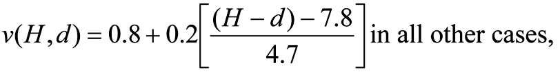
where:
v(Hj, n, m, d) is to be taken as 1, if Hm coincides with the uppermost watertight boundary of the ship within the range (x1( …x2(-1)), and
v(Hj, n, 0, d) is to be taken as 0.
In no case is vm to be taken as less than zero or more than 1.
6.2. In general, each contribution dA to the index A in the case of horizontal subdivisions is obtained from the formula:

where:
vm = the v-value calculated in accordance with paragraph 6.1;
smin = the least s-factor for all combinations of damages obtained when the assumed damage extends from the assumed damage height Hm downwards.
1. For the purpose of the subdivision and damage stability calculations of the regulations, the permeability of each general compartment or part of a compartment shall be as follows:
Spaces | Permeability |
|---|---|
Appropriated to stores Occupied by accommodation Occupied by machinery Void spaces Intended for liquids | 0.60 0.95 0.85 0.95 0 or 0.951) |
2. For the purpose of the subdivision and damage stability calculations of the regulations, the permeability of each cargo compartment or part of a compartment shall be as follows:
Spaces | Permeability at draught ds | Permeability at draught dp | Permeability at draught dl |
|---|---|---|---|
Dry cargo spaces Container spaces Ro-ro spaces Cargo liquids | 0.70 0.70 0.90 0.70 | 0.80 0.80 0.90 0.80 | 0.95 0.95 0.95 0.95 |
3. Other figures for permeability may be used if substantiated by calculations.
1. A passenger ship intended to carry 400 or more persons shall have watertight subdivision abaft the collision bulkhead so that si = 1 for the three loading conditions on which is based the calculation of the subdivision index and for a damage involving all the compartments within 0.08L measured from the forward perpendicular.
2. A passenger ship intended to carry 36 or more persons is to be capable of withstanding damage along the side shell to an extent specified in paragraph 3.
Compliance with this regulation is to be achieved by demonstrating that si , as defined in regulation 7-2, is not less than 0.9 for the three loading conditions on which is based the calculation of the subdivision index.
3. The damage extent to be assumed when demonstrating compliance with paragraph 2, is to be dependent on both N as defined in regulation 6, and Ls as defined in regulation 2, such that:
.1. the vertical extent of damage is to extend from the ship’s moulded baseline to a position up to 12.5 m above the position of the deepest subdivision draught as defined in regulation 2, unless a lesser vertical extent of damage were to give a lower value of si , in which case this reduced extent is to be used;
.2. where 400 or more persons are to be carried, a damage length of 0.03Ls but not less than 3 m is to be assumed at any position along the side shell, in conjunction with a penetration inboard of 0.1B but not less than 0.75 m measured inboard from the ship side, at right angle to the centreline at the level of the deepest subdivision draught;
.3. where less than 400 persons are carried, damage length is to be assumed at any position along the shell side between transverse watertight bulkheads provided that the distance between two adjacent transverse watertight bulkheads is not less than the assumed damage length. If the distance between adjacent transverse watertight bulkheads is less than the assumed damage length, only one of these bulkheads shall be considered effective for the purpose of demonstrating compliance with paragraph 2;
.4. where 36 persons are carried, a damage length of 0.015Ls but not less than 3 m is to be assumed, in conjunction with a penetration inboard of 0.05B but not less than 0.75 m; and
.5. where more than 36, but fewer than 400 persons are carried the values of damage length and penetration inboard, used in the determination of the assumed extent of damage, are to be obtained by linear interpolation between the values of damage length and penetration which apply for ships carrying 36 persons and 400 persons as specified in subparagraphs .4 and .2.
1. A double bottom shall be fitted extending from the collision bulkhead to the afterpeak bulkhead, as far as this is practicable and compatible with the design and proper working of the ship.
2. Where a double bottom is required to be fitted the inner bottom shall be continued out to the ship’s sides in such a manner as to protect the bottom to the turn of the bilge.
Such protection will be deemed satisfactory if the inner bottom is not lower at any part than a plane parallel with the keel line and which is located not less than a vertical distance h measured from the keel line, as calculated by the formula:
h = B/20
However, in no case is the value of h to be less than 760 mm, and need not be taken as more than 2,000 mm.
3. Small wells constructed in the double bottom in connection with drainage arrangements of holds, etc., shall not extend downward more than necessary. A well extending to the outer bottom is, however, permitted at the after end of the shaft tunnel.
Other wells (e.g. for lubricating oil under main engines) may be permitted by the Administration if satisfied that the arrangements give protection equivalent to that afforded by a double bottom complying with this regulation. In no case shall the vertical distance from the bottom of such a well to a plane coinciding with the keel line be less than 500 mm.
4. A double bottom need not be fitted in way of watertight tanks, including dry tanks of moderate size, provided the safety of the ship is not impaired in the event of bottom or side damage.
5. In the case of passenger ships to which the provisions of regulation 1.5 apply and which are engaged on regular service within the limits of a short international voyage as defined in regulation III/3.22, the Administration may permit a double bottom to be dispensed with if satisfied that the fitting of a double bottom in that part would not be compatible with the design and proper working of the ship.
6. Any part of a passenger ship or a cargo ship that is not fitted with a double bottom in accordance with paragraphs 1, 4 or 5 shall be capable of withstanding bottom damages, as specified in paragraph 8, in that part of the ship.
7. In the case of unusual bottom arrangements in a passenger ship or a cargo ship, it shall be demonstrated that the ship is capable of withstanding bottom damages as specified in paragraph 8.
8. Compliance with paragraphs 6 or 7 is to be achieved by demonstrating that si , when calculated in accordance with regulation 7-2, is not less than 1 for all service conditions when subject to a bottom damage assumed at any position along the ship’s bottom and with an extent specified in .2 below for the affected part of the ship:
.1. Flooding of such spaces shall not render emergency power and lighting, internal communication, signals or other emergency devices inoperable in other parts of the ship.
.2. Assumed extent of damage shall be as follows:
For 0.3 L from the forward perpendicular of the ship | Any other part of the ship | |
|---|---|---|
Longitudinal extent | 1/3 L2/3 or 14.5 m, whichever is less | 1/3 L2/3 or 14.5 m, whichever is less |
Transverse extent | B/6 or 10 m, whichever is less | B/6 or 5 m, whichever is less |
Vertical extent, measured from the keel line | B/20 or 2 m, whichever is less | B/20 or 2 m, whichever is less |
.3. If any damage of a lesser extent than the maximum damage specified in .2 would result in a more severe condition, such damage should be considered.
9. In case of large lower holds in passenger ships, the Administration may require an increased double bottom height of not more than B/10 or 3 m, whichever is less, measured from the keel line. Alternatively, bottom damages may be calculated for these areas, in accordance with paragraph 8, but assuming an increased vertical extent.
1. Each watertight subdivision bulkhead, whether transverse or longitudinal, shall be constructed having scantlings as specified in regulation 2.17. In all cases, watertight subdivision bulkheads shall be capable of supporting at least the pressure due to a head of water up to the bulkhead deck.
2. Steps and recesses in watertight bulkheads shall be as strong as the bulkhead at the place where each occurs.
1. Testing watertight spaces not intended to hold liquids and cargo holds intended to hold ballast by filling them with water is not compulsory. When testing by filling with water is not carried out, a hose test shall be carried out where practicable. This test shall be carried out in the most advanced stage of the fitting out of the ship. Where a hose test is not practicable because of possible damage to machinery, electrical equipment insulation or outfitting items, it may be replaced by a careful visual examination of welded connections, supported where deemed necessary by means such as a dye penetrant test or an ultrasonic leak test or an equivalent test. In any case a thorough inspection of the watertight bulkheads shall be carried out.
2. The forepeak, double bottom (including duct keels) and inner skins shall be tested with water to a head corresponding to the requirements of regulation 10.1.
3. Tanks which are intended to hold liquids, and which form part of the watertight subdivision of the ship, shall be tested for tightness and structural strength with water to a head corresponding to its design pressure. The water head is in no case to be less than the top of the air pipes or to a level of 2.4 m above the top of the tank, whichever is the greater.
4. The tests referred to in paragraphs 2 and 3 are for the purpose of ensuring that the subdivision structural arrangements are watertight and are not to be regarded as a test of the fitness of any compartment for the storage of oil fuel or for other special purposes for which a test of a superior character may be required depending on the height to which the liquid has access in the tank or its connections.
1. A collision bulkhead shall be fitted which shall be watertight up to the bulkhead deck. This bulkhead shall be located at a distance from the forward perpendicular of not less than 0.05L or 10 m, whichever is the less, and, except as may be permitted by the Administration, not more than 0.08L or 0.05L + 3 m, whichever is the greater.
2. Where any part of the ship below the waterline extends forward of the forward perpendicular, e.g. a bulbous bow, the distances stipulated in paragraph 1 shall be measured from a point either:
.1. at the mid-length of such extension;
.2. at a distance 0.015L forward of the forward perpendicular; or
.3. at a distance 3 m forward of the forward perpendicular, whichever gives the smallest measurement.
3. The bulkhead may have steps or recesses provided they are within the limits prescribed in paragraph 1 or 2.
4. No doors, manholes, access openings, ventilation ducts or any other openings shall be fitted in the collision bulkhead below the bulkhead deck.
5.1. Except as provided in paragraph 5.2, the collision bulkhead may be pierced below the bulkhead deck by not more than one pipe for dealing with fluid in the forepeak tank, provided that the pipe is fitted with a screw-down valve capable of being operated from above the bulkhead deck, the valve chest being secured inside the forepeak to the collision bulkhead. The Administration may, however, authorize the fitting of this valve on the after side of the collision bulkhead provided that the valve is readily accessible under all service conditions and the space in which it is located is not a cargo space. All valves shall be of steel, bronze or other approved ductile material. Valves of ordinary cast iron or similar material are not acceptable.
5.2. If the forepeak is divided to hold two different kinds of liquids the Administration may allow the collision bulkhead to be pierced below the bulkhead by two pipes, each of which is fitted as required by paragraph 5.1, provided the Administration is satisfied that there is no practical alternative to the fitting of such a second pipe and that, having regard to the additional subdivision provided in the forepeak, the safety of the ship is maintained.
6. Where a long forward superstructure is fitted the collision bulkhead shall be extended weathertight to the deck next above the bulkhead deck. The extension need not be fitted directly above the bulkhead below provided it is located within the limits prescribed in paragraph 1 or 2 with the exception permitted by paragraph 7 and that the part of the deck which forms the step is made effectively weathertight. The extension shall be so arranged as to preclude the possibility of the bow door causing damage to it in the case of damage to, or detachment of, a bow door.
7. Where bow doors are fitted and a sloping loading ramp forms part of the extension of the collision bulkhead above the bulkhead deck the ramp shall be weathertight over its complete length. In cargo ships the part of the ramp which is more than 2.3 m above the bulkhead deck may extend forward of the limit specified in paragraph 1 or 2. Ramps not meeting the above requirements shall be disregarded as an extension of the collision bulkhead.
8. The number of openings in the extension of the collision bulkhead above the freeboard deck shall be restricted to the minimum compatible with the design and normal operation of the ship. All such openings shall be capable of being closed weathertight.
9. Bulkheads shall be fitted separating the machinery space from cargo and accommodation spaces forward and aft and made watertight up to the bulkhead deck. In passenger ships an afterpeak bulkhead shall also be fitted and made watertight up to the bulkhead deck. The afterpeak bulkhead may, however, be stepped below the bulkhead deck, provided the degree of safety of the ship as regards subdivision is not thereby diminished.
10. In all cases stern tubes shall be enclosed in watertight spaces of moderate volume.
In passenger ships the stern gland shall be situated in a watertight shaft tunnel or other watertight space separate from the stern tube compartment and of such volume that, if flooded by leakage through the stern gland, the bulkhead deck will not be immersed. In cargo ships other measures to minimize the danger of water penetrating into the ship in case of damage to stern tube arrangements may be taken at the discretion of the Administration.
1. The number of openings in watertight bulkheads shall be reduced to the minimum compatible with the design and proper working of the ship, satisfactory means shall be provided for closing these openings.
2.1. Where pipes, scuppers, electric cables, etc., are carried through watertight bulkheads, arrangements shall be made to ensure the watertight integrity of the bulkheads.
2.2. Valves not forming part of a piping system shall not be permitted in watertight bulkheads.
2.3. Lead or other heat sensitive materials shall not be used in systems which penetrate watertight bulkheads, where deterioration of such systems in the event of fire would impair the watertight integrity of the bulkheads.
3. No doors, manholes, or access openings are permitted in watertight transverse bulkheads dividing a cargo space from an adjoining cargo space, except as provided in paragraph 9.1 and in regulation 14.
4. Subject to paragraph 10, not more than one door, apart from the doors to shaft tunnels, may be fitted in each watertight bulkhead within spaces containing the main and auxiliary propulsion machinery including boilers serving the needs of propulsion. Where two or more shafts are fitted, the tunnels shall be connected by an intercommunicating passage. There shall be only one door between the machinery space and the tunnel spaces where two shafts are fitted and only two doors where there are more than two shafts. All these doors shall be of the sliding type and shall be so located as to have their sills as high as practicable. The hand gear for operating these doors from above the bulkhead deck shall be situated outside the spaces containing the machinery.
5.1. Watertight doors, except as provided in paragraph 9.1 or regulation 14, shall be power-operated sliding doors complying with the requirements of paragraph 7 capable of being closed simultaneously from the central operating console at the navigation bridge in not more than 60 s with the ship in the upright position.
5.2. The means of operation whether by power or by hand of any power-operated sliding watertight door shall be capable of closing the door with the ship listed to 15° either way. Consideration shall also be given to the forces which may act on either side of the door as may be experienced when water is flowing through the opening applying a static head equivalent to a water height of at least 1 m above the sill on the centreline of the door.
5.3. Watertight door controls, including hydraulic piping and electric cables, shall be kept as close as practicable to the bulkhead in which the doors are fitted, in order to minimize the likelihood of them being involved in any damage which the ship may sustain. The positioning of watertight doors and their controls shall be such that if the ship sustains damage within one fifth of the breadth of the ship, as defined in regulation 2, such distance being measured at right angles to the centreline at the level of the deepest subdivision draught, the operation of the watertight doors clear of the damaged portion of the ship is not impaired.
6. All power-operated sliding watertight doors shall be provided with means of indication which will show at all remote operating positions whether the doors are open or closed. Remote operating positions shall only be at the navigation bridge as required by paragraph 7.1.5 and at the location where hand operation above the bulkhead deck is required by paragraph 7.1.4.
7.1. Each power-operated sliding watertight door:
.1. shall have a vertical or horizontal motion;
.2. shall, subject to paragraph 10, be normally limited to a maximum clear opening width of 1.2 m. The Administration may permit larger doors only to the extent considered necessary for the effective operation of the ship provided that other safety measures, including the following, are taken into consideration:
.1. special consideration shall be given to the strength of the door and its closing appliances in order to prevent leakages; and
.2. the door shall be located inboard the damage zone B/5;
.3. shall be fitted with the necessary equipment to open and close the door using electric power, hydraulic power, or any other form of power that is acceptable to the Administration;
.4. shall be provided with an individual hand-operated mechanism. It shall be possible to open and close the door by hand at the door itself from either side, and in addition, close the door from an accessible position above the bulkhead deck with an all round crank motion or some other movement providing the same degree of safety acceptable to the Administration.
Direction of rotation or other movement is to be clearly indicated at all operating positions. The time necessary for the complete closure of the door, when operating by hand gear, shall not exceed 90 s with the ship in the upright position;
.5. shall be provided with controls for opening and closing the door by power from both sides of the door and also for closing the door by power from the central operating console at the navigation bridge;
.6. shall be provided with an audible alarm, distinct from any other alarm in the area, which will sound whenever the door is closed remotely by power and which shall sound for at least 5 s but no more than 10 s before the door begins to move and shall continue sounding until the door is completely closed. In the case of remote hand operation it is sufficient for the audible alarm to sound only when the door is moving. Additionally, in passenger areas and areas of high ambient noise the Administration may require the audible alarm to be supplemented by an intermittent visual signal at the door; and
.7. shall have an approximately uniform rate of closure under power. The closure time, from the time the door begins to move to the time it reaches the completely closed position, shall in no case be less than 20 s or more than 40 s with the ship in the upright position.
7.2. The electrical power required for power-operated sliding watertight doors shall be supplied from the emergency switchboard either directly or by a dedicated distribution board situated above the bulkhead deck. The associated control, indication and alarm circuits shall be supplied from the emergency switchboard either directly or by a dedicated distribution board situated above the bulkhead deck and be capable of being automatically supplied by the transitional source of emergency electrical power required by regulation 42.3.1.3 in the event of failure of either the main or emergency source of electrical power.
7.3. Power-operated sliding watertight doors shall have either:
.1. a centralized hydraulic system with two independent power sources each consisting of a motor and pump capable of simultaneously closing all doors. In addition, there shall be for the whole installation hydraulic accumulators of sufficient capacity to operate all the doors at least three times, i.e. closed-open-closed, against an adverse list of 15º. This operating cycle shall be capable of being carried out when the accumulator is at the pump cut-in pressure. The fluid used shall be chosen considering the temperatures liable to be encountered by the installation during its service. The power operating system shall be designed to minimize the possibility of having a single failure in the hydraulic piping adversely affect the operation of more than one door. The hydraulic system shall be provided with a low-level alarm for hydraulic fluid reservoirs serving the power-operated system and a low gas pressure alarm or other effective means of monitoring loss of stored energy in hydraulic accumulators. These alarms are to be audible and visual and shall be situated on the central operating console at the navigation bridge; or
.2. an independent hydraulic system for each door with each power source consisting of a motor and pump capable of opening and closing the door.
In addition, there shall be a hydraulic accumulator of sufficient capacity to operate the door at least three times, i.e. closed-open-closed, against an adverse list of 15°. This operating cycle shall be capable of being carried out when the accumulator is at the pump cut-in pressure. The fluid used shall be chosen considering the temperatures liable to be encountered by the installation during its service. A low gas pressure group alarm or other effective means of monitoring loss of stored energy in hydraulic accumulators shall be provided at the central operating console on the navigation bridge. Loss of stored energy indication at each local operating position shall also be provided; or
.3. an independent electrical system and motor for each door with each power source consisting of a motor capable of opening and closing the door. The power source shall be capable of being automatically supplied by the transitional source of emergency electrical power as required by regulation 42.4.2 – in the event of failure of either the main or emergency source of electrical power and with sufficient capacity to operate the door at least three times, i.e. closed-open-closed, against an adverse list of 15°.
For the systems specified in paragraphs 7.3.1, 7.3.2 and 7.3.3, provision should be made as follows: Power systems for power-operated watertight sliding doors shall be separate from any other power system. A single failure in the electric or hydraulic power-operated systems excluding the hydraulic actuator shall not prevent the hand operation of any door.
7.4. Control handles shall be provided at each side of the bulkhead at a minimum height of 1.6 m above the floor and shall be so arranged as to enable persons passing through the doorway to hold both handles in the open position without being able to set the power closing mechanism in operation accidentally. The direction of movement of the handles in opening and closing the door shall be in the direction of door movement and shall be clearly indicated.
7.5. As far as practicable, electrical equipment and components for watertight doors shall be situated above the bulkhead deck and outside hazardous areas and spaces.
7.6. The enclosures of electrical components necessarily situated below the bulkhead deck shall provide suitable protection against the ingress of water.6)
7.7. Electric power, control, indication and alarm circuits shall be protected against fault in such a way that a failure in one door circuit will not cause a failure in any other door circuit. Short circuits or other faults in the alarm or indicator circuits of a door shall not result in a loss of power operation of that door. Arrangements shall be such that leakage of water into the electrical equipment located below the bulkhead deck will not cause the door to open.
7.8. A single electrical failure in the power operating or control system of a power-operated sliding watertight door shall not result in a closed door opening.
Availability of the power supply should be continuously monitored at a point in the electrical circuit as near as practicable to each of the motors required by paragraph 7.3.
Loss of any such power supply should activate an audible and visual alarm at the central operating console at the navigation bridge.
8.1. The central operating console at the navigation bridge shall have a “master mode” switch with two modes of control: a “local control” mode which shall allow any door to be locally opened and locally closed after use without automatic closure, and a “doors closed” mode which shall automatically close any door that is open. The “doors closed” mode shall automatically close any door that is open. The “doors closed” mode shall permit doors to be opened locally and shall automatically re-close the doors upon release of the local control mechanism. The “master mode” switch shall normally be in the “local control” mode. The “doors closed” mode shall only be used in an emergency or for testing purposes. Special consideration shall be given to the reliability of the “master mode” switch.
8.2. The central operating console at the navigation bridge shall be provided with a diagram showing the location of each door, with visual indicators to show whether each door is open or closed. A red light shall indicate a door is fully open and a green light shall indicate a door is fully closed. When the door is closed remotely the red light shall indicate the intermediate position by flashing. The indicating circuit shall be independent of the control circuit for each door.
8.3. It shall not be possible to remotely open any door from the central operating console.
9.1. If the Administration is satisfied that such doors are essential, watertight doors of satisfactory construction may be fitted in watertight bulkheads dividing cargo between deck spaces. Such doors may be hinged, rolling or sliding doors but shall not be remotely controlled. They shall be fitted at the highest level and as far from the shell plating as practicable, but in no case shall the outboard vertical edges be situated at a distance from the shell plating which is less than one fifth of the breadth of the ship, as defined in regulation 2, such distance being measured at right angles to the centreline at the level of the deepest subdivision draught.
9.2. Should any such doors be accessible during the voyage, they shall be fitted with a device which prevents unauthorized opening. When it is proposed to fit such doors, the number and arrangements shall receive the special consideration of the Administration.
10. Portable plates on bulkheads shall not be permitted except in machinery spaces.
The Administration may permit not more than one power-operated sliding watertight door in each watertight bulkhead larger than those specified in paragraph 7.1.2 to be substituted for these portable plates, provided these doors are intended to remain closed during navigation except in case of urgent necessity at the discretion of the master. These doors need not meet the requirements of paragraph 7.1.4 regarding complete closure by hand-operated gear in 90 s.
11.1. Where trunkways or tunnels for access from crew accommodation to the stokehold, for piping, or for any other purpose are carried through watertight bulkheads, they shall be watertight and in accordance with the requirements of regulation 16-1. The access to at least one end of each such tunnel or trunkway, if used as a passage at sea, shall be through a trunk extending watertight to a height sufficient to permit access above the bulkhead deck. The access to the other end of the trunkway or tunnel may be through a watertight door of the type required by its location in the ship. Such trunkways or tunnels shall not extend through the first subdivision bulkhead abaft the collision bulkhead.
11.2. Where it is proposed to fit tunnels piercing watertight bulkheads, these shall receive the special consideration of the Administration.
11.3. Where trunkways in connection with refrigerated cargo and ventilation or forced draught trunks are carried through more than one watertight bulkhead, the means of closure at such openings shall be operated by power and be capable of being closed from a central position situated above the bulkhead deck.
1. The number of openings in watertight subdivisions is to be kept to a minimum compatible with the design and proper working of the ship. Where penetrations of watertight bulkheads and internal decks are necessary for access, piping, ventilation, electrical cables, etc., arrangements are to be made to maintain the watertight integrity.
The Administration may permit relaxation in the watertightness of openings above the freeboard deck, provided that it is demonstrated that any progressive flooding can be easily controlled and that the safety of the ship is not impaired.
2. Doors provided to ensure the watertight integrity of internal openings which are used while at sea are to be sliding watertight doors capable of being remotely closed from the bridge and are also to be operable locally from each side of the bulkhead. Indicators are to be provided at the control position showing whether the doors are open or closed, and an audible alarm is to be provided at the door closure. The power, control and indicators are to be operable in the event of main power failure. Particular attention is to be paid to minimizing the effect of control system failure. Each power-operated sliding watertight door shall be provided with an individual hand-operated mechanism. It shall be possible to open and close the door by hand at the door itself from both sides.
3. Access doors and access hatch covers normally closed at sea, intended to ensure the watertight integrity of internal openings, shall be provided with means of indication locally and on the bridge showing whether these doors or hatch covers are open or closed.
A notice is to be affixed to each such door or hatch cover to the effect that it is not to be left open.
4. Watertight doors or ramps of satisfactory construction may be fitted to internally subdivide large cargo spaces, provided that the Administration is satisfied that such doors or ramps are essential. These doors or ramps may be hinged, rolling or sliding doors or ramps, but shall not be remotely controlled.7) Should any of the doors or ramps be accessible during the voyage, they shall be fitted with a device which prevents unauthorized opening.
5. Other closing appliances which are kept permanently closed at sea to ensure the watertight integrity of internal openings shall be provided with a notice which is to be affixed to each such closing appliance to the effect that it is to be kept closed. Manholes fitted with closely bolted covers need not be so marked.
1. This regulation applies to passenger ships designed or adapted for the carriage of goods vehicles and accompanying personnel.
2. If in such a ship the total number of passengers which include personnel accompanying vehicles does not exceed 12 + Ad /25, where Ad = total deck area (square metres) of spaces available for the stowage of goods vehicles and where the clear height at the stowage position and at the entrance to such spaces is not less than 4 m, the provisions of regulations 13.9.1 and 13.9.2 in respect of watertight doors apply except that the doors may be fitted at any level in watertight bulkheads dividing cargo spaces.
Additionally, indicators are required on the navigation bridge to show automatically when each door is closed and all door fastenings are secured.
3. The ship may not be certified for a higher number of passengers than assumed in paragraph 2, if a watertight door has been fitted in accordance with this regulation.
1. The number of openings in the shell plating shall be reduced to the minimum compatible with the design and proper working of the ship.
2. The arrangement and efficiency of the means for closing any opening in the shell plating shall be consistent with its intended purpose and the position in which it is fitted and generally to the satisfaction of the Administration.
3.1. Subject to the requirements of the International Convention on Load Lines in force, no sidescuttle shall be fitted in such a position that its sill is below a line drawn parallel to the bulkhead deck at side and having its lowest point 2.5% of the breadth of the ship above the deepest subdivision draught, or 500 mm, whichever is the greater.
3.2. All sidescuttles the sills of which are below the bulkhead deck of passenger ships and the freeboard deck of cargo ships, as permitted by paragraph 3.1, shall be of such construction as will effectively prevent any person opening them without the consent of the master of the ship.
4. Efficient hinged inside deadlights so arranged that they can be easily and effectively closed and secured watertight, shall be fitted to all sidescuttles except that abaft one eighth of the ship’s length from the forward perpendicular and above a line drawn parallel to the bulkhead deck at side and having its lowest point at a height of 3.7 m plus 2.5% of the breadth of the ship above the deepest subdivision draught, the deadlights may be portable in passenger accommodation other than that for steerage passengers, unless the deadlights are required by the International Convention on Load Lines in force to be permanently attached in their proper positions. Such portable deadlights shall be stowed adjacent to the sidescuttles they serve.
5.1. No sidescuttles shall be fitted in any spaces which are appropriated exclusively to the carriage of cargo or coal.
5.2. Sidescuttles may, however, be fitted in spaces appropriated alternatively to the carriage of cargo or passengers, but they shall be of such construction as will effectively prevent any person opening them or their deadlights without the consent of the master.
6. Automatic ventilating sidescuttles shall not be fitted in the shell plating below the bulkhead deck of passenger ships and the freeboard deck of cargo ships without the special sanction of the Administration.
7. The number of scuppers, sanitary discharges and other similar openings in the shell plating shall be reduced to the minimum either by making each discharge serve for as many as possible of the sanitary and other pipes, or in any other satisfactory manner.
8.1. All inlets and discharges in the shell plating shall be fitted with efficient and accessible arrangements for preventing the accidental admission of water into the ship.
8.2.1. Subject to the requirements of the International Convention on Load Lines in force, and except as provided in paragraph 8.3, each separate discharge led through the shell plating from spaces below the bulkhead deck of passenger ships and the freeboard deck of cargo ships shall be provided with either one automatic non-return valve fitted with a positive means of closing it from above the bulkhead deck or with two automatic non-return valves without positive means of closing, provided that the inboard valve is situated above the deepest subdivision draught and is always accessible for examination under service conditions. Where a valve with positive means of closing is fitted, the operating position above the bulkhead deck shall always be readily accessible and means shall be provided for indicating whether the valve is open or closed.
8.2.2. The requirements of the International Convention on Load Lines in force shall apply to discharges led through the shell plating from spaces above the bulkhead deck of passenger ships and the freeboard deck of cargo ships.
8.3. Machinery space, main and auxiliary sea inlets and discharges in connection with the operation of machinery shall be fitted with readily accessible valves between the pipes and the shell plating or between the pipes and fabricated boxes attached to the shell plating. In manned machinery spaces the valves may be controlled locally and shall be provided with indicators showing whether they are open or closed.
8.4. Moving parts penetrating the shell plating below the deepest subdivision draught shall be fitted with a watertight sealing arrangement acceptable to the Administration.
The inboard gland shall be located within a watertight space of such volume that, if flooded, the bulkhead deck will not be submerged. The Administration may require that if such compartment is flooded, essential or emergency power and lighting, internal communication, signals or other emergency devices must remain available in other parts of the ship.
8.5. All shell fittings and valves required by this regulation shall be of steel, bronze or other approved ductile material. Valves of ordinary cast iron or similar material are not acceptable. All pipes to which this regulation refers shall be of steel or other equivalent material to the satisfaction of the Administration.
9. Gangway, cargo and fuelling ports fitted below the bulkhead deck of passenger ships and the freeboard deck of cargo ships shall be watertight and in no case be so fitted as to have their lowest point below the deepest subdivision draught.
10.1. The inboard opening of each ash-chute, rubbish-chute, etc., shall be fitted with an efficient cover.
10.2. If the inboard opening is situated below the bulkhead deck of passenger ships and the freeboard deck of cargo ships, the cover shall be watertight and, in addition, an automatic non-return valve shall be fitted in the chute in an easily accessible position above the deepest subdivision draught.
1. All external openings leading to compartments assumed intact in the damage analysis, which are below the final damage waterline, are required to be watertight.
2. External openings required to be watertight in accordance with paragraph 1 shall, except for cargo hatch covers, be fitted with indicators on the bridge.
3. Openings in the shell plating below the deck limiting the vertical extent of damage shall be fitted with a device that prevents unauthorized opening if they are accessible during the voyage.
4. Other closing appliances which are kept permanently closed at sea to ensure the watertight integrity of external openings shall be provided with a notice affixed to each appliance to the effect that it is to be kept closed. Manholes fitted with closely bolted covers need not be so marked.
1. In all ships:
.1. the design, materials and construction of all watertight doors, sidescuttles, gangway and cargo ports, valves, pipes, ash-chutes and rubbish-chutes referred to in these regulations shall be to the satisfaction of the Administration;
.2. such valves, doors and mechanisms shall be suitably marked to ensure that they may be properly used to provide maximum safety; and
.3. the frames of vertical watertight doors shall have no groove at the bottom in which dirt might lodge and prevent the door closing properly.
2. In passenger ships and cargo ships watertight doors shall be tested by water pressure to a head of water they might sustain in a final or intermediate stage of flooding.
Where testing of individual doors is not carried out because of possible damage to insulation or outfitting items, testing of individual doors may be replaced by a prototype pressure test of each type and size of door with a test pressure corresponding at least to the head required for the intended location. The prototype test shall be carried out before the door is fitted. The installation method and procedure for fitting the door on board shall correspond to that of the prototype test. When fitted on board, each door shall be checked for proper seating between the bulkhead, the frame and the door.
1. Watertight decks, trunks, tunnels, duct keels and ventilators shall be of the same strength as watertight bulkheads at corresponding levels. The means used for making them watertight, and the arrangements adopted for closing openings in them, shall be to the satisfaction of the Administration. Watertight ventilators and trunks shall be carried at least up to the bulkhead deck in passenger ships and up to the freeboard deck in cargo ships.
2. Where a ventilation trunk passing through a structure penetrates the bulkhead deck, the trunk shall be capable of withstanding the water pressure that may be present within the trunk, after having taken into account the maximum heel angle allowable during intermediate stages of flooding, in accordance with regulation 7-2.
3. Where all or part of the penetration of the bulkhead deck is on the main ro-ro deck, the trunk shall be capable of withstanding impact pressure due to internal water motions (sloshing) of water trapped on the ro-ro deck.
4. After completion, a hose or flooding test shall be applied to watertight decks and a hose test to watertight trunks, tunnels and ventilators.
1. The Administration may require that all reasonable and practicable measures shall be taken to limit the entry and spread of water above the bulkhead deck. Such measures may include partial bulkheads or webs. When partial watertight bulkheads and webs are fitted on the bulkhead deck, above or in the immediate vicinity of watertight bulkheads, they shall have watertight shell and bulkhead deck connections so as to restrict the flow of water along the deck when the ship is in a heeled damaged condition. Where the partial watertight bulkhead does not line up with the bulkhead below, the bulkhead deck between shall be made effectively watertight. Where openings, pipes, scuppers, electric cables etc. are carried through the partial watertight bulkheads or decks within the immersed part of the bulkhead deck, arrangements shall be made to ensure the watertight integrity of the structure above the bulkhead deck.8)
2. All openings in the exposed weather deck shall have coamings of ample height and strength and shall be provided with efficient means for expeditiously closing them weathertight. Freeing ports, open rails and scuppers shall be fitted as necessary for rapidly clearing the weather deck of water under all weather conditions.
3. The open end of air pipes terminating within a superstructure shall be at least 1 m above the waterline when the ship heels to an angle of 15º, or the maximum angle of heel during intermediate stages of flooding, as determined by direct calculation, whichever is the greater. Alternatively, air pipes from tanks other than oil tanks may discharge through the side of the superstructure. The provisions of this paragraph are without prejudice to the provisions of the International Convention on Load Lines in force.
4. Sidescuttles, gangway, cargo and fuelling ports and other means for closing openings in the shell plating above the bulkhead deck shall be of efficient design and construction and of sufficient strength having regard to the spaces in which they are fitted and their positions relative to the deepest subdivision draught.9)
5. Efficient inside deadlights, so arranged that they can be easily and effectively closed and secured watertight, shall be provided for all sidescuttles to spaces below the first deck above the bulkhead deck.
1.1. Subject to the provisions of paragraphs 1.2 and 1.3, all accesses that lead to spaces below the bulkhead deck shall have a lowest point which is not less than 2.5 m above the bulkhead deck.
1.2. Where vehicle ramps are installed to give access to spaces below the bulkhead deck, their openings shall be able to be closed weathertight to prevent ingress of water below, alarmed and indicated to the navigation bridge.
1.3. The Administration may permit the fitting of particular accesses to spaces below the bulkhead deck provided they are necessary for the essential working of the ship, e.g. the movement of machinery and stores, subject to such accesses being made watertight, alarmed and indicated on the navigation bridge.
2. Indicators shall be provided on the navigation bridge for all shell doors, loading doors and other closing appliances which, if left open or not properly secured, could, in the opinion of the Administration, lead to flooding of a special category space or ro-ro space. The indicator system shall be designed on the fail-safe principle and shall show by visual alarms if the door is not fully closed or if any of the securing arrangements are not in place and fully locked and by audible alarms if such door or closing appliances become open or the securing arrangements become unsecured. The indicator panel on the navigation bridge shall be equipped with a mode selection function “harbour/sea voyage” so arranged that an audible alarm is given on the navigation bridge if the ship leaves harbour with the bow doors, inner doors, stern ramp or any other side shell doors not closed or any closing device not in the correct position. The power supply for the indicator system shall be independent of the power supply for operating and securing the doors.
3. Television surveillance and a water leakage detection system shall be arranged to provide an indication to the navigation bridge and to the engine control station of any leakage through inner and outer bow doors, stern doors or any other shell doors which could lead to flooding of special category spaces or ro-ro spaces.
1. In order that the required degree of subdivision shall be maintained, a load line corresponding to the approved subdivision draught shall be assigned and marked on the ship’s sides. A ship intended for alternating modes of operation may, if the owners desire, have one or more additional load lines assigned and marked to correspond with the subdivision draughts which the Administration may approve for the alternative service configurations. Each service configuration so approved shall comply with part B-1 of this chapter independently of the results obtained for other modes of operation.
2. The subdivision load lines assigned and marked shall be recorded in the Passenger Ship Safety Certificate, and shall be distinguished by the notation P1 for the principal passenger service configuration, and P2, P3, etc., for the alternative configurations. The principal passenger configuration shall be taken as the mode of operation in which the required subdivision index R will have the highest value.
3. The freeboard corresponding to each of these load lines shall be measured at the same position and from the same deck line as the freeboards determined in accordance with the International Convention on Load Lines in force.
4. The freeboard corresponding to each approved subdivision load line and the service configuration, for which it is approved, shall be clearly indicated on the Passenger Ship Safety Certificate.
5. In no case shall any subdivision load line mark be placed above the deepest load line in salt water as determined by the strength of the ship or the International Convention on Load Lines in force.
6. Whatever may be the position of the subdivision load line marks, a ship shall in no case be loaded so as to submerge the load line mark appropriate to the season and locality as determined in accordance with the International Convention on Load Lines in force.
7. A ship shall in no case be so loaded that when it is in salt water the subdivision load line mark appropriate to the particular voyage and service configuration is submerged.
1. There shall be permanently exhibited, or readily available on the navigation bridge, for the guidance of the officer in charge of the ship, plans showing clearly for each deck and hold the boundaries of the watertight compartments, the openings therein with the means of closure and position of any controls thereof, and the arrangements for the correction of any list due to flooding. In addition, booklets containing the aforementioned information shall be made available to the officers of the ship.10)
2. Watertight doors in passenger ships permitted to remain open during navigation shall be clearly indicated in the ship’s stability information.
3. General precautions to be included shall consist of a listing of equipment, conditions, and operational procedures, considered by the Administration to be necessary to maintain watertight integrity under normal ship operations.
4. Specific precautions to be included shall consist of a listing of elements (i.e. closures, security of cargo, sounding of alarms, etc.) considered by the Administration to be vital to the survival of the ship, passengers and crew.
5. In case of ships to which damage stability requirements of part B-1 apply, damage stability information shall provide the master a simple and easily understandable way of assessing the ship’s survivability in all damage cases involving a compartment or group of compartments.11)
1. On completion of loading of the ship and prior to its departure, the master shall determine the ship’s trim and stability and also ascertain and record that the ship is in compliance with stability criteria in relevant regulations. The determination of the ship’s stability shall always be made by calculation. The Administration may accept the use of an electronic loading and stability computer or equivalent means for this purpose.
2. Water ballast should not in general be carried in tanks intended for oil fuel. In ships in which it is not practicable to avoid putting water in oil fuel tanks, oily-water separating equipment to the satisfaction of the Administration shall be fitted, or other alternative means, such as discharge to shore facilities, acceptable to the Administration shall be provided for disposing of the oily-water ballast.
3. The provisions of this regulation are without prejudice to the provisions of the International Convention for the Prevention of Pollution from Ships in force.
1. Drills for the operating of watertight doors, sidescuttles, valves and closing mechanisms of scuppers, ash-chutes and rubbish-chutes shall take place weekly. In ships in which the voyage exceeds one week in duration a complete drill shall be held before leaving port, and others thereafter at least once a week during the voyage.
2. All watertight doors, both hinged and power operated, in watertight bulkheads, in use at sea, shall be operated daily.
3. The watertight doors and all mechanisms and indicators connected therewith, all valves, the closing of which is necessary to make a compartment watertight, and all valves the operation of which is necessary for damage control cross connections shall be periodically inspected at sea at least once a week.
4. A record of all drills and inspections required by this regulation shall be entered in the log-book with an explicit record of any defects which may be disclosed.
1. All watertight doors shall be kept closed during navigation except that they may be opened during navigation as specified in paragraphs 3 and 4. Watertight doors of a width of more than 1.2 m in machinery spaces as permitted by regulation 13.10 may only be opened in the circumstances detailed in that regulation. Any door which is opened in accordance with this paragraph shall be ready to be immediately closed.
2. Watertight doors located below the bulkhead deck having a maximum clear opening width of more than 1.2 m shall be kept closed when the ship is at sea, except for limited periods when absolutely necessary as determined by the Administration.
3. A watertight door may be opened during navigation to permit the passage of passengers or crew, or when work in the immediate vicinity of the door necessitates it being opened. The door must be immediately closed when transit through the door is complete or when the task which necessitated it being open is finished.
4. Certain watertight doors may be permitted to remain open during navigation only if considered absolutely necessary; that is, being open is determined essential to the safe and effective operation of the ship’s machinery or to permit passengers normally unrestricted access throughout the passenger area. Such determination shall be made by the Administration only after careful consideration of the impact on ship operations and survivability. A watertight door permitted to remain thus open shall be clearly indicated in the ship’s stability information and shall always be ready to be immediately closed.
5. Portable plates on bulkheads shall always be in place before the ship leaves port, and shall not be removed during navigation except in case of urgent necessity at the discretion of the master. The necessary precautions shall be taken in replacing them to ensure that the joints are watertight. Power-operated sliding watertight doors permitted in machinery spaces in accordance with regulation 13.10 shall be closed before the ship leaves port and shall remain closed during navigation except in case of urgent necessity at the discretion of the master.
6. Watertight doors fitted in watertight bulkheads dividing cargo between deck spaces in accordance with regulation 13.9.1 shall be closed before the voyage commences and shall be kept closed during navigation; the time of opening such doors in port and of closing them before the ship leaves port shall be entered in the log-book.
7. Gangway, cargo and fuelling ports fitted below the bulkhead deck shall be effectively closed and secured watertight before the ship leaves port, and shall be kept closed during navigation.
8. The following doors, located above the bulkhead deck, shall be closed and locked before the ship proceeds on any voyage and shall remain closed and locked until the ship is at its next berth:
.1. cargo loading doors in the shell or the boundaries of enclosed superstructures;
.2. bow visors fitted in positions as indicated in paragraph 8.1;
.3. cargo loading doors in the collision bulkhead; and
.4. ramps forming an alternative closure to those defined in paragraphs 8.1 to 8.3 inclusive.
9. Provided that where a door cannot be opened or closed while the ship is at the berth such a door may be opened or left open while the ship approaches or draws away from the berth, but only so far as may be necessary to enable the door to be immediately operated. In any case, the inner bow door must be kept closed.
10. Notwithstanding the requirements of paragraphs 8.1 and 8.4, the Administration may authorize that particular doors can be opened at the discretion of the master, if necessary for the operation of the ship or the embarking and disembarking of passengers when the ship is at safe anchorage and provided that the safety of the ship is not impaired.
11. The master shall ensure that an effective system of supervision and reporting of the closing and opening of the doors referred to in paragraph 8 is implemented.
12. The master shall ensure, before the ship proceeds on any voyage, that an entry in the log-book is made of the time of the last closing of the doors specified in paragraph 13 and the time of any opening of particular doors in accordance with paragraph 14.
13. Hinged doors, portable plates, sidescuttles, gangway, cargo and bunkering ports and other openings, which are required by these regulations to be kept closed during navigation, shall be closed before the ship leaves port. The time of closing and the time of opening (if permissible under these regulations) shall be recorded in such log-book as may be prescribed by the Administration.
14. Where in a between-decks, the sills of any of the sidescuttles referred to in regulation 15.3.2 are below a line drawn parallel to the bulkhead deck at side and having its lowest point 1.4 m plus 2.5% of the breadth of the ship above the water when the ship departs from any port, all the sidescuttles in that between-decks shall be closed watertight and locked before the ship leaves port, and they shall not be opened before the ship arrives at the next port. In the application of this paragraph the appropriate allowance for fresh water may be made when applicable.
.1. The time of opening such sidescuttles in port and of closing and locking them before the ship leaves port shall be entered in such log-book as may be prescribed by the Administration.
.2. For any ship that has one or more sidescuttles so placed that the requirements of paragraph 15 would apply when it was floating at its deepest subdivision draught, the Administration may indicate the limiting mean draught at which these sidescuttles will have their sills above the line drawn parallel to the bulkhead deck at side, and having its lowest point 1.4 m plus 25% of the breadth of the ship above the waterline corresponding to the limiting mean draught, and at which it will there fore be permissible to depart from port without previously closing and locking them and to open them at sea on the responsibility of the master during the voyage to the next port. In tropical zones as defined in the International Convention on Load Lines in force, this limiting draught may be increased by 0.3 m.
15. Sidescuttles and their deadlights which will not be accessible during navigation shall be closed and secured before the ship leaves port.
16. If cargo is carried in such spaces, the sidescuttles and their deadlights shall be closed watertight and locked before the cargo is shipped and such closing and locking shall be recorded in such log-book as may be prescribed by the Administration.
17. When a rubbish-chute, etc. is not in use, both the cover and the valve required by regulation 15.10.2 shall be kept closed and secured.
1. Special category spaces and ro-ro spaces shall be continuously patrolled or monitored by effective means, such as television surveillance, so that any movement of vehicles in adverse weather conditions and unauthorized access by passengers thereto can be detected whilst the ship is underway.
2. Documented operating procedures for closing and securing all shell doors, loading doors and other closing appliances which, if left open or not properly secured, could, in the opinion of the Administration, lead to flooding of a special category space or ro-ro space, shall be kept on board and posted at an appropriate place.
3. All accesses from the ro-ro deck and vehicle ramps that lead to spaces below the bulkhead deck shall be closed before the ship leaves the berth on any voyage and shall remain closed until the ship is at its next berth.
4. The master shall ensure that an effective system of supervision and reporting of the closing and opening of such accesses referred to in paragraph 3 is implemented.
5. The master shall ensure, before the ship leaves the berth on any voyage, that an entry in the log-book, as required by regulation 22.13, is made of the time of the last closing of the accesses referred to in paragraph 3.
6. Notwithstanding the requirements of paragraph 3, the Administration may permit some accesses to be opened during the voyage, but only for a period sufficient to permit through passage and, if required, for the essential working of the ship.
7. All transverse or longitudinal bulkheads which are taken into account as effective to confine the seawater accumulated on the ro-ro deck shall be in place and secured before the ship leaves the berth and remain in place and secured until the ship is at its next berth.
8. Notwithstanding the requirements of paragraph 7, the Administration may permit some accesses within such bulkheads to be opened during the voyage but only for sufficient time to permit through passage and, if required, for the essential working of the ship.
9. In all ro-ro passenger ships, the master or the designated officer shall ensure that, without the expressed consent of the master or the designated officer, no passengers are allowed access to an enclosed ro-ro deck when the ship is under way.
1. Openings in the shell plating below the deck limiting the vertical extent of damage shall be kept permanently closed while at sea.
2. Notwithstanding the requirements of paragraph 3, the Administration may authorize that particular doors may be opened at the discretion of the master, if necessary for the operation of the ship and provided that the safety of the ship is not impaired.
3. Watertight doors or ramps fitted internally subdivide large cargo spaces shall be closed before the voyage commences and shall be kept closed during navigation; the time of opening such doors in port and of closing them before the ship leaves port shall be entered in the log-book.
4. The use of access doors and hatch covers intended to ensure the watertight integrity of internal openings shall be authorized by the officer of the watch.
1. Single hold cargo ships other than bulk carriers constructed before 1 January 2007 shall comply with the requirements of this regulation not later than 31 December 2009.
2. Ships having a length (L) of less than 80 m, or 100 m if constructed before 1 July 1998, and a single cargo hold below the freeboard deck or cargo holds below the freeboard deck which are not separated by at least one bulkhead made watertight up to that deck, shall be fitted in such space or spaces with water level detectors12) .
3. The water level detectors required by paragraph 2 shall:
.1. give an audible and visual alarm at the navigation bridge when the water level above the inner bottom in the cargo hold reaches a height of not less than 0.3 m, and another when such level reaches not more than 15% of the mean depth of the cargo hold; and
.2. be fitted at the aft end of the hold, or above its lowest part where the inner bottom is not parallel to the designed waterline. Where webs or partial watertight bulkheads are fitted above the inner bottom, Administrations may require the fitting of additional detectors.
4. The water level detectors required by paragraph 2 need not be fitted in ships complying with regulation XII/12, or in ships having watertight side compartments each side of the cargo hold length extending vertically at least from inner bottom to freeboard deck.”
2. The following new regulation 35-1 is inserted after existing regulation 35:
1. This regulation applies to ships constructed on or after 1 January 2009.
2. Passenger ships and cargo ships
2.1. An efficient bilge pumping system shall be provided, capable of pumping from and draining any watertight compartment other than a space permanently appropriated for the carriage of fresh water, water ballast, oil fuel or liquid cargo and for which other efficient means of pumping are provided, under all practical conditions. Efficient means shall be provided for draining water from insulated holds.
2.2. Sanitary, ballast and general service pumps may be accepted as independent power bilge pumps if fitted with the necessary connections to the bilge pumping system.
2.3. All bilge pipes used in or under coal bunkers or fuel storage tanks or in boiler or machinery spaces, including spaces in which oil-settling tanks or oil fuel pumping units are situated, shall be of steel or other suitable material.
2.4. The arrangement of the bilge and ballast pumping system shall be such as to prevent the possibility of water passing from the sea and from water ballast spaces into the cargo and machinery spaces, or from one compartment to another. Provision shall be made to prevent any deep tank having bilge and ballast connections being inadvertently flooded from the sea when containing cargo, or being discharged through a bilge pump when containing water ballast.
2.5. All distribution boxes and manually operated valves in connection with the bilge pumping arrangements shall be in positions which are accessible under ordinary circumstances.
2.6. Provision shall be made for the drainage of enclosed cargo spaces situated on the bulkhead deck of a passenger ship and on the freeboard deck of a cargo ship, provided that the Administration may permit the means of drainage to be dispensed with in any particular compartment of any ship or class of ship if it is satisfied that by reason of size or internal subdivision of those spaces the safety of the ship is not thereby impaired.
2.6.1. Where the freeboard to the bulkhead deck or the freeboard deck, respectively, is such that the deck edge is immersed when the ship heels more than 5°, the drainage shall be by means of a sufficient number of scuppers of suitable size discharging directly overboard, fitted in accordance with the requirements of regulation 15 in the case of a passenger ship and the requirements for scuppers, inlets and discharges of the International Convention on Load Lines in force in the case of a cargo ship.
2.6.2. Where the freeboard is such that the edge of the bulkhead deck or the edge of the freeboard deck, respectively, is immersed when the ship heels 5° or less, the drainage of the enclosed cargo spaces on the bulkhead deck or on the freeboard deck, respectively, shall be led to a suitable space, or spaces, of adequate capacity, having a high water level alarm and provided with suitable arrangements for discharge overboard. In addition it shall be ensured that:
.1. the number, size and disposition of the scuppers are such as to prevent unreasonable accumulation of free water;
.2. the pumping arrangements required by this regulation for passenger ships or cargo ships, as applicable, take account of the requirements for any fixed pressure water-spraying fire extinguishing system;
.3. water contaminated with petrol or other dangerous substances is not drained to machinery spaces or other spaces where sources of ignition may be present; and
.4. where the enclosed cargo space is protected by a carbon dioxide fire extinguishing system the deck scuppers are fitted with means to prevent the escape of the smothering gas.
3. Passenger ships
3.1. The bilge pumping system required by paragraph 2.1 shall be capable of operation under all practicable conditions after a casualty whether the ship is upright or listed. For this purpose wing suctions shall generally be fitted except in narrow compartments at the end of the ship where one suction may be sufficient. In compartments of unusual form, additional suctions may be required. Arrangements shall be made whereby water in the compartment may find its way to the suction pipes. Where, for particular compartments, the Administration is satisfied that the provision of drainage may be undesirable, it may allow such provision to be dispensed with if calculations made in accordance with the conditions laid down in regulations 7 and 8 show that the survival capability of the ship will not be impaired.
3.2. At least three power pumps shall be fitted connected to the bilge main, one of which may be driven by the propulsion machinery. Where the bilge pump numeral is 30 or more, one additional independent power pump shall be provided.
The bilge pump numeral shall be calculated as follows:
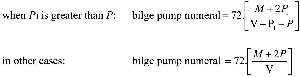
where:
L = the length of the ship (metres), as defined in regulation 2;
M = the volume of the machinery space (cubic metres), as defined in regulation 2, that is below the bulkhead deck; with the addition thereto of the volume of any permanent oil fuel bunkers which may be situated above the inner bottom and forward of, or abaft, the machinery space;
P = the whole volume of the passenger and crew spaces below the bulkhead deck (cubic metres), which are provided for the accommodation and use of passengers and crew, excluding baggage, store, provision and mail rooms;
V = the whole volume of the ship below the bulkhead deck (cubic metres);
P1 = KN,
where:
N = the number of passengers for which the ship is to be certified; and
K = 0.056L
However, where the value of KN is greater than the sum of P and the whole volume of the actual passenger spaces above the bulkhead deck, the figure to be taken as P1 is that sum or two-thirds KN, whichever is the greater.
3.3. Where practicable, the power bilge pumps shall be placed in separate watertight compartments and so arranged or situated that these compartments will not be flooded by the same damage. If the main propulsion machinery, auxiliary machinery and boilers are in two or more watertight compartments, the pumps available for bilge service shall be distributed as far as is possible throughout these compartments.
3.4. On a ship of 91.5 m in length and upwards or having a bilge pump numeral, calculated in accordance with paragraph 3.2, of 30 or more, the arrangements shall be such that at least one power bilge pump shall be available for use in all flooding conditions which the ship is required to withstand, as follows:
.1. one of the required bilge pumps shall be an emergency pump of a reliable submersible type having a source of power situated above the bulkhead deck; or
.2. the bilge pumps and their sources of power shall be so distributed throughout the length of the ship that at least one pump in an undamaged compartment will be available.
3.5. With the exception of additional pumps which may be provided for peak compartments only, each required bilge pump shall be so arranged as to draw water from any space required to be drained by paragraph 2.1.
3.6. Each power bilge pump shall be capable of pumping water through the required main bilge pipe at a speed of not less than 2 m/s. Independent power bilge pumps situated in machinery spaces shall have direct suctions from these spaces, except that not more than two such suctions shall be required in any one space. Where two or more such suctions are provided, there shall be at least one on each side of the ship. The Administration may require independent power bilge pumps situated in other spaces to have separate direct suctions. Direct suctions shall be suitably arranged and those in a machinery space shall be of a diameter not less than that required for the bilge main.
3.7.1. In addition to the direct bilge suction or suctions required by paragraph 3.6, a direct suction from the main circulating pump leading to the drainage level of the machinery space and fitted with a non-return valve shall be provided in the machinery space. The diameter of this direct suction pipe shall be at least two thirds of the diameter of the pump inlet in the case of steamships, and of the same diameter as the pump inlet in the case of motorships.
3.7.2. Where in the opinion of the Administration the main circulating pump is not suitable for this purpose, a direct emergency bilge suction shall be led from the largest available independent power driven pump to the drainage level of the machinery space; the suction shall be of the same diameter as the main inlet of the pump used. The capacity of the pump so connected shall exceed that of a required bilge pump by an amount deemed satisfactory by the Administration.
3.7.3. The spindles of the sea inlet and direct suction valves shall extend well above the engine-room platform.
3.8. All bilge suction piping up to the connection to the pumps shall be independent of other piping.
3.9. The diameter d of the bilge main shall be calculated according to the following formula. However, the actual internal diameter of the bilge main may be rounded off to the nearest standard size acceptable to the Administration:
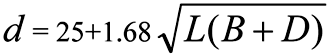
where:
d is the internal diameter of the bilge main (millimetres);
L and B are the length and the breadth of the ship (metres) as defined in regulation 2; and
D is the moulded depth of the ship to the bulkhead deck (metres) provided that, in a ship having an enclosed cargo space on the bulkhead deck which is internally drained in accordance with the requirements of paragraph 2.6.2 and which extends for the full length of the ship, D shall be measured to the next deck above the bulkhead deck. Where the enclosed cargo spaces cover a lesser length, D shall be taken as the moulded depth to the bulkhead deck plus lh/L where l and h are the aggregate length and height respectively of the enclosed cargo spaces (metres).
The diameter of the bilge branch pipes shall meet the requirements of the Administration.
3.10. Provision shall be made to prevent the compartment served by any bilge suction pipe being flooded in the event of the pipe being severed or otherwise damaged by collision or grounding in any other compartment. For this purpose, where the pipe is at any part situated nearer the side of the ship than one fifth of the breadth of the ship (as defined in regulation 2 and measured at right angles to the centreline at the level of the deepest subdivision load line), or is in a duct keel, a non-return valve shall be fitted to the pipe in the compartment containing the open end.
3.11. Distribution boxes, cocks and valves in connection with the bilge pumping system shall be so arranged that, in the event of flooding, one of the bilge pumps may be operative on any compartment; in addition, damage to a pump or its pipe connecting to the bilge main outboard of a line drawn at one fifth of the breadth of the ship shall not put the bilge system out of action. If there is only one system of pipes common to all the pumps, the necessary valves for controlling the bilge suctions must be capable of being operated from above the bulkhead deck. Where in addition to the main bilge pumping system an emergency bilge pumping system is provided, it shall be independent of the main system and so arranged that a pump is capable of operating on any compartment under flooding condition as specified in paragraph 3.1; in that case only the valves necessary for the operation of the emergency system need be capable of being operated from above the bulkhead deck.
3.12. All cocks and valves referred to in paragraph 3.11 which can be operated from above the bulkhead deck shall have their controls at their place of operation clearly marked and shall be provided with means to indicate whether they are open or closed.
4. Cargo ships
At least two power pumps connected to the main bilge system shall be provided, one of which may be driven by the propulsion machinery. If the Administration is satisfied that the safety of the ship is not impaired, bilge pumping arrangements may be dispensed with in particular compartments.”
3. In paragraph 5.2.4, the reference to “regulation II-1/25-9.2” is replaced by the reference to “regulation II-1/13-1.2”.
4. In paragraph 2.2.4.1.2, the reference to “regulation II-1/21” is replaced by the reference to “regulation II-1/35-1”.
5. In paragraph 6.1.4.1.3, the reference to “regulation II-1/21” is replaced by the reference to “regulation II-1/35-1”, and in paragraph 6.1.4.2, the reference to “regulation II-1/22” is replaced by the reference to “regulation II-1/5-1”.
6. In subparagraph 2.1, the reference to “regulation II-1/22” is replaced by the reference to “regulation II-1/5-1”.
7. In paragraph 3, the reference to “regulation II-1/2.12” is replaced by the reference to “regulation II-1/2.22”.
8. The reference to “regulation II-1/2.12” is replaced by the reference to “regulation II-1/2.22”.
9. The following new regulation 3-1 is added after the existing regulation 3:
1. This regulation applies to Companies and registered owners of ships to which chapter I applies.
2. For the purpose of this regulation, registered owner shall be as specified by the Administration and Company as defined in regulation IX/l.
3. Every Company and registered owner shall be provided with an identification number which conforms to the IMO Unique Company and Registered Owner Identification Number Scheme adopted by the Organization13) .
4. The Company identification number shall be inserted on the certificates and certified copies thereof issued under regulation IX/4 and section A/19.2 or A/19.4 of the ISPS Code.
5. This regulation shall take effect when the certificates referred to in paragraph 4 are issued or renewed on or after 1 January 2009.”
10. In paragraph 3, in the first sentence, after the word “information”, the following words are inserted:
“(The Continuous Synopsis Record shall contain the information in paragraphs 3.7 and 3.10 when it is issued or updated on or after 1 January 2009)”;
and the following new subparagraphs .7 and .10 are inserted as follows:
“.7. the registered owner identification number;” and
“.10. the Company identification number;”.
11. In paragraph 3, existing subparagraphs .7 and .8 are renumbered as subparagraphs .8 and .9, and existing subparagraphs .9 to .13 are renumbered as subparagraphs .11 to .15.
Resolutie MSC.201(81) van 18 mei 2006
Bij Resolutie MSC.201(81) heeft de Maritieme Veiligheidscommissie van de Internationale Maritieme Organisatie op 18 mei 2006 in overeenstemming met artikel VIII(b)(iv) van het Verdrag wijzigingen aangenomen. De Engelse tekst1) van de Resolutie en de wijzigingen luidt als volgt:
(adopted on 18 May 2006)
Adoption of Amendments to the International Convention for the Safety of Life at Sea, 1974, as amended
The Maritime Safety Committee,
Recalling Article 28(b) of the Convention on the International Maritime Organization concerning the functions of the Committee,
Recalling further article VIII(b) of the International Convention for the Safety of Life at Sea (SOLAS), 1974 (hereinafter referred to as “the Convention”), concerning the amendment procedure applicable to the Annex to the Convention, other than the provisions of chapter I thereof,
Having considered, at its eighty-first session, amendments to the Convention, proposed and circulated in accordance with article VIII(b)(i) thereof,
1. Adopts, in accordance with article VIII(b)(iv) of the Convention, amendments to the Convention, the text of which is set out in the Annex to the present resolution;
2. Determines, in accordance with article VIII(b)(vi)(2)(bb) of the Convention, that the said amendments shall be deemed to have been accepted on 1 January 2010, unless, prior to that date, more than one third of the Contracting Governments to the Convention or Contracting Governments the combined merchant fleets of which constitute not less than 50% of the gross tonnage of the world’s merchant fleet, have notified their objections to the amendments;
3. Invites SOLAS Contracting Governments to note that, in accordance with article VIII(b)(vii)(2) of the Convention, the amendments shall enter into force on 1 July 2010 upon their acceptance in accordance with paragraph 2 above;
4. Requests the Secretary-General, in conformity with article VIII(b)(v) of the Convention, to transmit certified copies of the present resolution and the text of the amendments contained in the Annex to all Contracting Governments to the Convention;
5. Further requests the Secretary-General to transmit copies of this resolution and its Annex to Members of the Organization, which are not Contracting Governments to the Convention.
1. In subparagraph .2 of paragraph 4.1.3.3, “.” is replaced by “; or”.
2. In paragraph 4.1.3.3, the following new subparagraph .3 is added after the existing subparagraph .2:
“.3. water-mist nozzles that have been tested and approved in accordance with the guidelines approved by the Organization1) .”
3. In regulation II-2/15, as amended by resolution MSC.31(63), the text after the title is replaced by the following:
“(Paragraphs 2.9 to 2.12 of this regulation apply to ships constructed on or after 1. February 1992, except that the references to paragraphs 2.10 and 2.11 in paragraphs 3 and 4 apply to ships constructed on or after 1 July 1998)”.
4. In paragraph 2.1, the following new subparagraphs .1 and .2 are inserted:
“.1. for passenger ships on voyages less than 24 h, a number of infant lifejackets equal to at least 2.5% of the number of passengers on board shall be provided;
.2. for passenger ships on voyages 24 h or greater, infant lifejackets shall be provided for each infant on board;”,
and the existing subparagraphs .1 and .2 are renumbered as subparagraphs .3 and .4. The word “and” is moved from the end of renumbered subparagraph .3 to the end of renumbered subparagraph .4.
5. The following new subparagraph .5 is inserted after the renumbered subparagraph .4 of paragraph 2.1:
“.5. if the adult lifejackets provided are not designed to fit persons weighing up to 140 kg and with a chest girth of up to 1,750 mm, a sufficient number of suitable accessories shall be available on board to allow them to be secured to such persons.”
6. The existing text of subparagraph .6.1 of paragraph 1 is replaced by the following:
“.6.1. capable of transmitting a distress alert through the polar orbiting satellite service operating in the 406 MHz band;”
7. The existing text of subparagraph .3.3 of paragraph 1 is replaced by the following:
“.3.3. through the Inmarsat geostationary satellite service by a ship earth station.”
8. The existing text of subparagraph .4.3 of paragraph 1 is replaced by the following:
“.4.3. through the Inmarsat geostationary satellite service by an additional ship earth station.”
9. The existing text of subparagraph .3.2 of paragraph 2 is replaced by the following:
“.3.2. through the Inmarsat geostationary satellite service by a ship earth station; and”
10. The following new paragraph 4 is added after the existing paragraph 3:
“4. Notwithstanding the requirements of paragraphs 1.1, 1.3, 1.4 and 1.5, ballast water exchange may be undertaken provided that:
.1. the master has determined that it is safe to do so and takes into consideration any increased blind sectors or reduced horizontal fields of vision resulting from the operation to ensure that a proper lookout is maintained at all times;
.2. the operation is conducted in accordance with the ship’s ballast water management plan, taking into account the recommendations on ballast water exchange adopted by the Organization; and
.3. the commencement and termination of the operation are recorded in the ship’s record of navigational activities pursuant to regulation 28.”
Resolutie MSC.202(81) van 19 mei 2006
Bij Resolutie MSC.202(81) heeft de Maritieme Veiligheidscommissie van de Internationale Maritieme Organisatie op 19 mei 2006 in overeenstemming met artikel VIII(b)(iv) van het Verdrag wijzigingen aangenomen. De Engelse tekst1) van de Resolutie en de wijzigingen luidt als volgt:
(adopted on 19 May 2006)
Adoption of Amendments to the International Convention for the Safety of Life at Sea, 1974, as amended
The Maritime Safety Committee,
Recalling Article 28(b) of the Convention on the International Maritime Organization concerning the functions of the Committee,
Recalling further article VIII(b) of the International Convention for the Safety of Life at Sea (SOLAS), 1974 (hereinafter referred to as “the Convention”), concerning the amendment procedure applicable to the Annex to the Convention, other than the provisions of chapter I thereof,
Having considered, at its eighty-first session, amendments to the Convention, proposed and circulated in accordance with article VIII(b)(i) thereof,
1. Adopts, in accordance with article VIII(b)(iv) of the Convention, amendments to the Convention, the text of which is set out in the Annex to the present resolution;
2. Determines, in accordance with article VIII(b)(vi)(2)(bb) of the Convention, that the said amendments shall be deemed to have been accepted on 1 July 2007, unless, prior to that date, more than one third of the Contracting Governments to the Convention or Contracting Governments the combined merchant fleets of which constitute not less than 50% of the gross tonnage of the world’s merchant fleet, have notified their objections to the amendments;
3. Invites SOLAS Contracting Governments to note that, in accordance with article VIII(b)(vii)(2) of the Convention, the amendments shall enter into force on 1 January 2008 upon their acceptance in accordance with paragraph 2 above;
4. Requests the Secretary-General, in conformity with article VIII(b)(v) of the Convention, to transmit certified copies of the present resolution and the text of the amendments contained in the Annex to all Contracting Governments to the Convention;
5. Further requests the Secretary-General to transmit copies of this resolution and its Annex to Members of the Organization, which are not Contracting Governments to the Convention.
1. The following text is inserted after the existing paragraph 5:
“6. High-speed craft means a craft as defined in regulation X/1.3.
7. Mobile offshore drilling unit means a mobile offshore drilling unit as defined in regulation XI-2/1.1.5.”
2. The following new regulation 19-1 is inserted after the existing regulation 19:
1. Nothing in this regulation or the provisions of performance standards and functional requirements2) adopted by the Organization in relation to the long-range identification and tracking of ships shall prejudice the rights, jurisdiction or obligations of States under international law, in particular, the legal regimes of the high seas, the exclusive economic zone, the contiguous zone, the territorial seas or the straits used for international navigation and archipelagic sea lanes.
2.1. Subject to the provisions of paragraphs 4.1 and 4.2, this regulation shall apply to the following types of ships engaged on international voyages:
.1. passenger ships, including high-speed passenger craft;
.2. cargo ships, including high-speed craft, of 300 gross tonnage3) and upwards; and
.3. mobile offshore drilling units.
2.2. The term “ship”, when used in paragraphs 3 to 11.2, includes the passenger and cargo ships, the high-speed craft and the mobile offshore drilling units which are subject to the provisions of this regulation.
3. This regulation establishes provisions to enable Contracting Governments to undertake the long-range identification and tracking of ships.
4.1. Ships shall be fitted with a system to automatically transmit the information specified in paragraph 5 as follows:
.1. ships constructed on or after 31 December 2008;
.2. ships constructed before 31 December 2008 and certified for operations:
.1. in sea areas A1 and A2, as defined in regulations IV/2.1.12 and IV/2.1.13; or
.2. in sea areas Al, A2 and A3, as defined in regulations IV/2.1.12, IV/2.1.13 and IV/2.1.14;
not later than the first survey of the radio installation after 31 December 2008;
.3. ships constructed before 31 December 2008 and certified for operations in sea areas Al, A2, A3 and A4, as defined in regulations IV/2.1.12, IV/2.1.13, IV/2.1.14 and IV/2.1.15, not later than the first survey of the radio installation after 1 July 2009. However, these ships shall comply with the provisions of subparagraph .2 above whilst they operate within sea areas A1, A2 and A3.
4.2. Ships, irrespective of the date of construction, fitted with an automatic identification system (AIS), as defined in regulation 19.2.4, and operated exclusively within sea area A1, as defined in regulation IV/2.1.12, shall not be required to comply with the provisions of this regulation.
5. Subject to the provisions of paragraph 4.1, ships shall automatically transmit the following long-range identification and tracking information:
.1. the identity of the ship;
.2. the position of the ship (latitude and longitude); and
.3. the date and time of the position provided.
6. Systems and equipment used to meet the requirements of this regulation shall conform to performance standards and functional requirements4) not inferior to those adopted by the Organization. Any shipboard equipment shall be of a type approved by the Administration.
7. Systems and equipment used to meet the requirements of this regulation shall be capable of being switched off on board or be capable of ceasing the distribution of long-range identification and tracking information:
.1. where international agreements, rules or standards provide for the protection of navigational information; or
.2. in exceptional circumstances and for the shortest duration possible where the operation is considered by the master to compromise the safety or security of the ship. In such a case, the master shall inform the Administration without undue delay and make an entry in the record of navigational activities and incidents maintained in accordance with regulation 28 setting out the reasons for the decision and indicating the period during which the system or equipment was switched off.
8.1. Subject to the provisions of paragraphs 8.2 to 11.2, Contracting Governments shall be able to receive long-range identification and tracking information about ships, for security and other purposes as agreed by the Organization, as follows:
.1. the Administration shall be entitled to receive such information about ships entitled to fly its flag irrespective of where such ships may be located;
.2. a Contracting Government shall be entitled to receive such information about ships which have indicated their intention to enter a port facility, as defined in regulation XI-2/1.1.9, or a place under the jurisdiction of that Contracting Government, irrespective of where such ships may be located provided they are not located within the waters landward of the baselines,established in accordance with international law, of another Contracting Government; and
.3. a Contracting Government shall be entitled to receive such information about ships entitled to fly the flag of other Contracting Governments, not intending to enter a port facility or a place under the jurisdiction of that Contracting Government, navigating within a distance not exceeding 1,000 nautical miles of its coast provided such ships are not located within the waters landward of the baselines, established in accordance with international law, of another Contracting Government; and
.4. a Contracting Government shall not be entitled to receive, pursuant to subparagraph .3, such information about a ship located within the territorial sea of the Contracting Government whose flag the ship is entitled to fly.
8.2. Contracting Governments shall specify and communicate to the Organization relevant details, taking into account the performance standards and functional requirements adopted by the Organization5) , to enable long-range identification and tracking information to be made available pursuant to the provisions of paragraph 8.1.
The Contracting Government concerned may, at any time thereafter, amend or withdraw such communication. The Organization shall inform all Contracting Governments upon receipt of such communication together with the particulars thereof.
9.1. Notwithstanding the provisions of paragraph 8.1.3, the Administration shall be entitled, in order to meet security or other concerns, at any time, to decide that long-range identification and tracking information about ships entitled to fly its flag shall not be provided pursuant to the provisions of paragraph 8.1.3 to Contracting Governments. The Administration concerned may, at any time thereafter, amend, suspend or annul such decisions.
9.2. The Administration concerned shall communicate, pursuant to paragraph 9.1, such decisions to the Organization. The Organization shall inform all Contracting Governments upon receipt of such communication together with the particulars thereof.
9.3. The rights, duties and obligations, under international law, of the ships whose Administration invoked the provisions of paragraph 9.1 shall not be prejudiced as a result of such decisions.
10. Contracting Governments shall, at all times:
.1. recognize the importance of long-range identification and tracking information;
.2. recognize and respect the commercial confidentiality and sensitivity of any long-range identification and tracking information they may receive;
.3. protect the information they may receive from unauthorized access or disclosure; and
.4. use the information they may receive in a manner consistent with international law.
11.1. Contracting Governments shall bear all costs associated with any long-range identification and tracking information they request and receive. Notwithstanding the provisions of paragraph 11.2, Contracting Governments shall not impose any charges on ships in relation to the long-range identification and tracking information they may seek to receive.
11.2. Unless the national legislation of the Administration provides otherwise, ships entitled to fly its flag shall not incur any charges for transmitting long-range identification and tracking information in compliance with the provisions of this regulation.
12. Notwithstanding the provisions of paragraph 8.1, the search and rescue services of Contracting Governments shall be entitled to receive, free of any charges, long-range identification and tracking information in relation to the search and rescue of persons in distress at sea.
13. Contracting Governments may report to the Organization any case where they consider that provisions of this regulation or of any other related requirements established by the Organization have not been or are not being observed or adhered to.
14. The Maritime Safety Committee shall determine the criteria, procedures and arrangements for the establishment, review and audit of the provision of long-range identification and tracking information to Contracting Governments pursuant to the provisions of this regulation.”
Resolutie MSC.216(82) van 8 december 2006
Bij Resolutie MSC.216(82) heeft de Maritieme Veiligheidscommissie van de Internationale Maritieme Organisatie op 8 december 2006 in overeenstemming met artikel VIII(b)(iv) van het Verdrag wijzigingen aangenomen. De Engelse tekst1) van de Resolutie en de wijzigingen luidt als volgt:
(adopted on 8 December 2006)
Adoption of Amendments to the International Convention for the Safety of Life at Sea, 1974, as amended
The Maritime Safety Committee,
Recalling Article 28(b) of the Convention on the International Maritime Organization concerning the functions of the Committee,
Recalling further article VIII(b) of the International Convention for the Safety of Life at Sea (SOLAS), 1974 (hereinafter referred to as “the Convention”), concerning the amendment procedure applicable to the Annex to the Convention, other than to the provisions of chapter I thereof,
Having considered, at its eighty-second session, amendments to the Convention, proposed and circulated in accordance with article VIII(b)(i) thereof,
1. Adopts, in accordance with article VIII(b)(iv) of the Convention, amendments to the Convention, the text of which is set out in Annexes 1, 2 and 3 to the present resolution;
2. Determines, in accordance with article VIII(b)(vi)(2)(bb) of the Convention, that:
a) the said amendments, set out in Annex 1, shall be deemed to have been accepted on 1 January 2008;
b) the said amendments, set out in Annex 2, shall be deemed to have been accepted on 1 July 2008; and
c) the said amendments, set out in Annex 3, shall be deemed to have been accepted on 1 January 2010,
unless, prior to those dates, more than one third of the Contracting Governments to the Convention or Contracting Governments the combined merchant fleets of which constitute not less than 50% of the gross tonnage of the world’s merchant fleet, have notified their objections to the amendments;
3. Invites SOLAS Contracting Governments to note that, in accordance with article VIII(b)(vii)(2) of the Convention:
a) the amendments, set out in Annex 1, shall enter into force on 1 July 2008;
b) the amendments, set out in Annex 2, shall enter into force on 1 January 2009; and
c) the amendments, set out in Annex 3, shall enter into force on 1 July 2010,
upon their acceptance in accordance with paragraph 2 above;
4. Requests the Secretary-General, in conformity with article VIII(b)(v) of the Convention, to transmit certified copies of the present resolution and the text of the amendments contained in Annexes 1, 2 and 3 to all Contracting Governments to the Convention;
5. Further requests the Secretary-General to transmit copies of this resolution and its Annexes 1, 2 and 3 to Members of the Organization, which are not Contracting Governments to the Convention.
1. The existing text and the heading of regulation 3-2 are replaced by the following:
“Protective coatings of dedicated seawater ballast tanks in all types of ships and double-side skin spaces of bulk carriers
1. Paragraphs 2 and 4 of this regulation shall apply to ships of not less than 500 gross tonnage:
.1. for which the building contract is placed on or after 1 July 2008; or
.2. in the absence of a building contract, the keels of which are laid or which are at a similar stage of construction on or after 1 January 2009; or
.3. the delivery of which is on or after 1 July 2012.
2. All dedicated seawater ballast tanks arranged in ships and double-side skin spaces arranged in bulk carriers of 150 m in length and upwards shall be coated during construction in accordance with the Performance standard for protective coatings for dedicated seawater ballast tanks in all types of ships and double-side skin spaces of bulk carriers, adopted by the Maritime Safety Committee by resolution MSC.215(82), as may be amended by the Organization, provided that such amendments are adopted, brought into force and take effect in accordance with the provisions of article VIII of the present Convention concerning the amendment procedures applicable to the Annex other than chapter I.
3. All dedicated seawater ballast tanks arranged in oil tankers and bulk carriers constructed on or after 1 July 1998, for which paragraph 2 is not applicable, shall comply with the requirements of regulation II-1/3-2 adopted by resolution MSC.47(66).
4. Maintenance of the protective coating system shall be included in the overall ship’s maintenance scheme. The effectiveness of the protective coating system shall be verified during the life of a ship by the Administration or an organization recognized by the Administration, based on the guidelines developed by the Organization.1) ”
2. In paragraph 2.2.3, the second occurrence of the word “and” is deleted.
3. In paragraph 2.2.4, “.” is replaced by “; and”.
4. In paragraph 2.2, the following new subparagraph .5 is added after the existing subparagraph .4:
“.5. regulations 5.3.1.3.2 and 5.3.4 to passenger ships not later than the date of the first survey after 1 July 2008.”
5. The following new paragraph 53 is added after the existing paragraph 52:
“53. Cabin balcony is an open deck space which is provided for the exclusive use of the occupants of a single cabin and has direct access from such a cabin.”
6. The following text is added at the end of paragraph 5.2.3:
“except that “A-0” class standard is acceptable for windows and sidescuttles outside the limit specified in regulation 9.2.4.2.5.”
7. In paragraph 4.4, the words “or if applied on cabin balconies of passenger ships constructed on or after 1 July 2008,” are added between the words “stations” and “shall”.
8. In paragraph 3.1.2.1, the last sentence is deleted.
9. The following new paragraph 3.1.3 is inserted:
“3.1.3. Partial bulkheads and decks on passenger ships
3.1.3.1. Partial bulkheads or decks used to subdivide a space for utility or artistic treatment shall be of non-combustible materials.
3.1.3.2. Linings, ceilings and partial bulkheads or decks used to screen or to separate adjacent cabin balconies shall be of non-combustible materials. Cabin balconies on passenger ships constructed before 1 July 2008 shall comply with the requirements of this paragraph by the first survey after 1 July 2008.”
10. In the first sentence of paragraph 3.2.1.1, the words “and cabin balconies” are added between the words “spaces” and “which”, and the following new sentence is added at the end of the paragraph:
“However, the provisions of paragraph 3.2.3 need not be applied to cabin balconies.”
11. The following new subparagraph .3 is added to the existing paragraph 3.2.4.1:
“.3. exposed surfaces of cabin balconies, except for natural hard wood decking systems.”
12. The following new paragraph 3.4 is added after the existing paragraph 3.3:
“3.4. Furniture and furnishings on cabin balconies of passenger ships
On passenger ships, furniture and furnishings on cabin balconies shall comply with regulations 3.40.1, 3.40.2, 3.40.3, 3.40.6 and 3.40.7 unless such balconies are protected by a fixed pressure water-spraying and fixed fire detection and fire alarm systems complying with regulations 7.10 and 10.6.1.3. Passenger ships constructed before 1 July 2008 shall comply with the requirements of this paragraph by the first survey after 1 July 2008.”
13. The existing paragraph 2 is renumbered as paragraph 2.1.
14. The following new paragraph 2.2 is added after the renumbered paragraph 2.1:
“2.2. On passenger ships constructed on or after 1 July 2008, paints, varnishes and other finishes used on exposed surfaces of cabin balconies, excluding natural hard wood decking systems, shall not be capable of producing excessive quantities of smoke and toxic products, this being determined in accordance with the Fire Test Procedures Code.”
15. The existing paragraph 3 is renumbered as paragraph 3.1.
16. The following new paragraph 3.2 is added after the renumbered paragraph 3.1:
“3.2. On passenger ships constructed on or after 1 July 2008, primary deck coverings on cabin balconies shall not give rise to smoke, toxic or explosive hazards at elevated temperatures, this being determined in accordance with the Fire Test Procedures Code.”
17. The following new paragraph 10 is added after the existing paragraph 9.4:
“10. Protection of cabin balconies on passenger ships
A fixed fire detection and fire alarm system complying with the provisions of the Fire Safety Systems Code shall be installed on cabin balconies of ships to which regulation 5.3.4 applies, when furniture and furnishings on such balconies are not as defined in regulations 3.40.1, 3.40.2, 3.40.3, 3.40.6 and 3.40.7.”
18. The following new paragraph 2.2.6 is added after the existing paragraph 2.2.5.2:
“2.2.6. Arrangement of cabin balconies
On passenger ships constructed on or after 1 July 2008, non-load bearing partial bulkheads which separate adjacent cabin balconies shall be capable of being opened by the crew from each side for the purpose of fighting fires.”
19. The heading of paragraph 6.1 is replaced by the following:
“6.1. Sprinkler and water spray systems in passenger ships”
20. The following new paragraph 6.1.3 is added after the existing paragraph 6.1.2:
“6.1.3. A fixed pressure water-spraying fire-extinguishing system complying with the provisions of the Fire Safety Systems Code shall be installed on cabin balconies of ships to which regulation 5.3.4 applies, where furniture and furnishings on such balconies are not as defined in regulations 3.40.1, 3.40.2, 3.40.3, 3.40.6 and 3.40.7.”
21. Paragraph 4.3 is replaced by the following:
“4.3. The general emergency alarm system shall be audible throughout all the accommodation and normal crew working spaces. On passenger ships, the system shall also be audible on all open decks.”
22. In the first sentence of paragraph 7, the word “unfavourable” is replaced by the word “all” and the unit “°” is inserted after the terms “10” and “20”.
23. The words “, and if the inflated type, in a fully inflated condition at all times” are added at the end of subparagraph .1.
24. Paragraph 3.3.4 is replaced by the following:
“3.3.4. In the case of a lifeboat arranged for free-fall launching, at least once every three months during an abandon ship drill the crew shall board the lifeboat, properly secure themselves in their seats and commence launch procedures up to but not including the actual release of the lifeboat (i.e., the release hook shall not be released). The lifeboat shall then either be free-fall launched with only the required operating crew on board, or lowered into the water by means of the secondary means of launching with or without the operating crew on board. In both cases the lifeboat shall thereafter be manoeuvred in the water by the operating crew. At intervals of not more than six months, the lifeboat shall either be launched by free-fall with only the operating crew on board, or simulated launching shall be carried out in accordance with the guidelines developed by the Organization2) .”
25. Paragraphs 4.1 and 4.2 are replaced by the following:
“Falls used in launching shall be inspected periodically2) with special regard for areas passing through sheaves, and renewed when necessary due to deterioration of the falls or at intervals of not more than 5 years, whichever is the earlier.”
26. In the third sentence of paragraph 6.2, the words “it should be run for such period as prescribed in the manufacturer’s handbook” are replaced by the words “a suitable water supply may be provided”.
27. The heading of paragraph 8 is replaced by the following:
“8. Servicing of inflatable liferafts, inflatable lifejackets, marine evacuation systems and maintenance and repair of inflated rescue boats”
28. The second sentence of paragraph 11.1.3 is replaced by the following:
“The load to be applied shall be the mass of the survival craft or rescue boat without persons on board, except that, at intervals not exceeding five years, the test shall be carried out with a proof load equal to 1.1 times the weight of the survival craft or rescue boat and its full complement of persons and equipment.”
29. The chapeau of paragraph 11.2 is replaced by the following:
“11.2. Lifeboat or rescue boat on-load release gear, including free-fall lifeboat release systems, shall be:”
30. In the first sentence of paragraph 11.2.3, the word “lifeboat” is replaced by the word “boat”.
31. The following new paragraph 11.3 is added to the regulation:
“11.3. Davit-launched liferaft automatic release hooks shall be:
.1. maintained in accordance with instructions for on-board maintenance as required by regulation 36;
.2. subject to a thorough examination and operational test during the annual surveys required by regulations I/7 and I/8 by properly trained personnel familiar with the system; and
.3. operationally tested under a load of 1.1 times the total mass of the liferaft when loaded with its full complement of persons and equipment whenever the automatic release hook is overhauled. Such over-hauling and test shall be carried out at least once every five years.3) ”
32. The chapeau of paragraph 1.2 is replaced by the following:
“1.2. Passenger ships engaged on short international voyages shall carry:”
33. Paragraph 1.3 is deleted and the remaining paragraphs are renumbered accordingly.
34. In paragraph 1.4, the words “after all persons have been assembled, with lifejackets donned” are added at the end of the paragraph.
35. Paragraph 2.3 is replaced by the following:
“2.3. A lifeboat may be accepted as a rescue boat provided that it and its launching and recovery arrangements also comply with the requirements for a rescue boat.”
36. In paragraph 3.2, the words “and complying with the special standards of subdivision prescribed by regulation II-1/6.5” are deleted.
37. In paragraph 3.1, the words “approved by the Administration having regard for the recommendations approved by the Organization” are replaced by the words “complying with section 5.1.4 of the Code”.
38. In paragraph 3.2, all the words after the word “appliance” are replaced by the words “complying with section 6.1.7 of the Code”.
39. Subparagraph .2 of paragraph 1.1 is replaced by the following:
“.2. in addition, one or more inflatable or rigid liferafts, complying with the requirements of section 4.2 or 4.3 of the Code, of a mass of less than 185 kg and stowed in a position providing for easy side-to-side transfer at a single open deck level, and of such aggregate capacity as will accommodate the total number of persons on board. If the liferaft or liferafts are not of a mass of less than 185 kg and stowed in a position providing for easy side-to-side transfer at a single open deck level, the total capacity available on each side shall be sufficient to accommodate the total number of persons on board.”
40. Subparagraph .2 of paragraph 1.3 is replaced by the following:
“.2. unless the liferafts required by paragraph 1.3.1 are of a mass of less than 185 kg and stowed in a position providing for easy side-to-side transfer at a single open deck level, additional liferafts shall be provided so that the total capacity available on each side will accommodate 150% of the total number of persons on board;”
41. Subparagraph .4 of paragraph 1.3 is replaced by the following:
“.4. in the event of any one survival craft being lost or rendered unserviceable, there shall be sufficient survival craft available for use on each side, including any which are of a mass of less than 185 kg and stowed in a position providing for easy side-to-side transfer at a single open deck level, to accommodate the total number of persons on board.”
42. The second sentence of paragraph 2 is replaced by the following:
“A lifeboat may be accepted as a rescue boat, provided that it and its launching and recovery arrangements also comply with the requirements for a rescue boat.”
43. In the first sentence of paragraph 3.2, the words “of an appropriate size,” are inserted between the words “suits” and “complying”.
44. In paragraph 3.3, the words “including remotely located survival craft carried in accordance with regulation 31.1.4”, are inserted between the words “stowed,” and “additional” and the words “of an appropriate size” are inserted between the words “suits” and “shall”.
45. The following new paragraph 5 is added after the existing paragraph 4:
46. The existing paragraph 3 is deleted and the existing paragraphs 4 and 5 are renumbered as paragraphs 3 and 4.
49. In the Passenger Ship Safety Certificate, Cargo Ship Safety Construction Certificate and Cargo Ship Safety Certificate, the phrase “Date on which keel was laid or ship was at a similar stage of construction or, where applicable, date on which work for a conversion or an alteration or modification of a major character was commenced .....” is replaced by the following:
“Date of build:
– Date of building contract .........
– Date on which keel was laid or ship was at similar stage of construction .........
– Date of delivery .........
– Date on which work for a conversion or an alteration or modification of a major character was commenced (where applicable) .........
All applicable dates shall be completed.”
50. In the Record of Equipment for the Passenger Ship Safety Certificate (Form P), the following new item 4.2 is inserted in section 5 after item 4:
“4.2. Long-range identification and tracking system”,
and item 4 (Automatic identification system (AIS)) is renumbered as item 4.1.
51. In the Record of Equipment for the Cargo Ship Safety Equipment Certificate (Form E), the following new item 4.2 is inserted in section 3 after item 4:
“4.2. Long-range identification and tracking system”,
and item 4 (Automatic identification system (AIS)) is renumbered as item 4.1.
52. In the Record of Equipment for the Cargo Ship Safety Certificate (Form C), the following new item 4.2 is inserted in section 5 after item 4:
“4.2. Long-range identification and tracking system”,
and item 4 (Automatic identification system (AIS)) is renumbered as item 4.1.
53. In the table of paragraph 2.1.3, in the section commencing with the words “THIS IS TO CERTIFY:”, the reference to “regulation II-1/13” is replaced by the reference to “regulation II-1/18”.
1. The existing text of parts A, B and B-1 of the chapter is replaced by the following:
1.1. Unless expressly provided otherwise, this chapter shall apply to ships the keels of which are laid or which are at a similar stage of construction on or after 1 January 2009.
1.2. For the purpose of this chapter, the term a similar stage of construction means the stage at which:
.1. construction identifiable with a specific ship begins; and
.2. assembly of that ship has commenced comprising at least 50 tonnes or one per cent of the estimated mass of all structural material, whichever is less.
1.3. For the purpose of this chapter:
.1. the expression ships constructed means ships the keels of which are laid or which are at a similar stage of construction;
.2. the expression all ships means ships constructed before, on or after 1 January 2009;
.3. a cargo ship, whenever built, which is converted to a passenger ship shall be treated as a passenger ship constructed on the date on which such a conversion commences;
.4. the expression alterations and modifications of a major character means, in the context of cargo ship subdivision and stability, any modification to the construction which affects the level of subdivision of that ship. Where a cargo ship is subject to such modification, it shall be demonstrated that the A/R ratio calculated for the ship after such modifications is not less than the A/R ratio calculated for the ship before the modification.
However, in those cases where the ship’s A/R ratio before modification is equal to or greater than unity, it is only necessary that the ship after modification has an A value which is not less than R, calculated for the modified ship.
2. Unless expressly provided otherwise, for ships constructed before 1 January 2009, the Administration shall ensure that the requirements which are applicable under chapter II-1 of the International Convention for the Safety of Life at Sea, 1974, as amended by resolutions MSC.1(XLV), MSC.6(48), MSC.11(55), MSC.12(56), MSC.13(57), MSC.19(58), MSC.26(60), MSC.27(61), Resolution 1 of the 1995 SOLAS Conference, MSC.47(66), MSC.57(67), MSC.65(68), MSC.69(69), MSC.99(73), MSC.134(76), MSC.151(78) and MSC.170(79) are complied with.
3. All ships which undergo repairs, alterations, modifications and outfitting related thereto shall continue to comply with at least the requirements previously applicable to these ships. Such ships, if constructed before the date on which any relevant amendments enter into force, shall, as a rule, comply with the requirements for ships constructed on or after that date to at least the same extent as they did before undergoing such repairs, alterations, modifications or outfitting. Repairs, alterations and modifications of a major character and outfitting related thereto shall meet the requirements for ships constructed on or after the date on which any relevant amendments enter into force, in so far as the Administration deems reasonable and practicable.
4. The Administration of a State may, if it considers that the sheltered nature and conditions of the voyage are such as to render the application of any specific requirements of this chapter unreasonable or unnecessary, exempt from those requirements individual ships or classes of ships entitled to fly the flag of that State which, in the course of their voyage, do not proceed more than 20 miles from the nearest land.
5. In the case of passenger ships which are employed in special trades for the carriage of large numbers of special trade passengers, such as the pilgrim trade, the Administration of the State whose flag such ships are entitled to fly, if satisfied that it is impracticable to enforce compliance with the requirements of this chapter, may exempt such ships from those requirements, provided that they comply fully with the provisions of:
.1. the rules annexed to the Special Trade Passenger Ships Agreement, 1971; and
.2. the rules annexed to the Protocol on Space Requirements for Special Trade Passenger Ships, 1973.
For the purpose of this chapter, unless expressly provided otherwise:
1. Subdivision length (Ls) of the ship is the greatest projected moulded length of that part of the ship at or below deck or decks limiting the vertical extent of flooding with the ship at the deepest subdivision draught.
2. Mid-length is the mid-point of the subdivision length of the ship.
3. Aft terminal is the aft limit of the subdivision length.
4. Forward terminal is the forward limit of the subdivision length.
5. Length (L) is the length as defined in the International Convention on Load Lines in force.
6. Freeboard deck is the deck as defined in the International Convention on Load Lines in force.
7. Forward perpendicular is the forward perpendicular as defined in the International Convention on Load Lines in force.
8. Breadth (B) is the greatest moulded breadth of the ship at or below the deepest subdivision draught.
9. Draught (d) is the vertical distance from the keel line at mid-length to the waterline in question.
10. Deepest subdivision draught (ds) is the waterline which corresponds to the summer load line draught of the ship.
11. Light service draught (dl) is the service draught corresponding to the lightest anticipated loading and associated tankage, including, however, such ballast as may be necessary for stability and/or immersion. Passenger ships should include the full complement of passengers and crew on board.
12. Partial subdivision draught (dp) is the light service draught plus 60% of the difference between the light service draught and the deepest subdivision draught.
13. Trim is the difference between the draught forward and the draught aft, where the draughts are measured at the forward and aft terminals respectively, disregarding any rake of keel.
14. Permeability (μ) of a space is the proportion of the immersed volume of that space which can be occupied by water.
15. Machinery spaces are spaces between the watertight boundaries of a space containing the main and auxiliary propulsion machinery, including boilers, generators and electric motors primarily intended for propulsion. In the case of unusual arrangements, the Administration may define the limits of the machinery spaces.
16. Weathertight means that in any sea conditions water will not penetrate into the ship.
17. Watertight means having scantlings and arrangements capable of preventing the passage of water in any direction under the head of water likely to occur in intact and damaged conditions. In the damaged condition, the head of water is to be considered in the worst situation at equilibrium, including intermediate stages of flooding.
18. Design pressure means the hydrostatic pressure for which each structure or appliance assumed watertight in the intact and damage stability calculations is designed to withstand.
19. Bulkhead deck in a passenger ship means the uppermost deck at any point in the subdivision length (Ls ) to which the main bulkheads and the ship’s shell are carried watertight and the lowermost deck from which passenger and crew evacuation will not be impeded by water in any stage of flooding for damage cases defined in regulation 8 and in part B-2 of this chapter. The bulkhead deck may be a stepped deck. In a cargo ship the freeboard deck may be taken as the bulkhead deck.
20. Deadweight is the difference in tonnes between the displacement of a ship in water of a specific gravity of 1.025 at the draught corresponding to the assigned summer freeboard and the lightweight of the ship.
21. Lightweight is the displacement of a ship in tonnes without cargo, fuel, lubricating oil, ballast water, fresh water and feedwater in tanks, consumable stores, and passengers and crew and their effects.
22. Oil tanker is the oil tanker defined in regulation 1 of Annex I of the Protocol of 1978 relating to the International Convention for the Prevention of Pollution from Ships, 1973.
23. Ro-ro passenger ship means a passenger ship with ro-ro spaces or special category spaces as defined in regulation II-2/3.
24. Bulk carrier means a bulk carrier as defined in regulation XII/1.1.
25. Keel line is a line parallel to the slope of the keel passing amidships through:
.1. the top of the keel at centreline or line of intersection of the inside of shell plating with the keel if a bar keel extends below that line, on a ship with a metal shell; or
.2. in wood and composite ships, the distance is measured from the lower edge of the keel rabbet. When the form at the lower part of the midship section is of a hollow character, or where thick garboards are fitted, the distance is measured from the point where the line of the flat of the bottom continued inward intersects the centreline amidships.
26. Amidship is at the middle of the length (L).
For the purpose of parts C, D and E, unless expressly provided otherwise:
1. Steering gear control system is the equipment by which orders are transmitted from the navigating bridge to the steering gear power units. Steering gear control systems comprise transmitters, receivers, hydraulic control pumps and their associated motors, motor controllers, piping and cables.
2. Main steering gear is the machinery, rudder actuators, steering gear, power units, if any, and ancillary equipment and the means of applying torque to the rudder stock (e.g. tiller or quadrant) necessary for effecting movement of the rudder for the purpose of steering the ship under normal service conditions.
3. Steering gear power unit is:
.1. in the case of electric steering gear, an electric motor and its associated electrical equipment;
.2. in the case of electrohydraulic steering gear, an electric motor and its associated electrical equipment and connected pump; or
.3. in the case of other hydraulic steering gear, a driving engine and connected pump.
4. Auxiliary steering gear is the equipment other than any part of the main steering gear necessary to steer the ship in the event of failure of the main steering gear but not including the tiller, quadrant or components serving the same purpose.
5. Normal operational and habitable condition is a condition under which the ship as a whole, the machinery, services, means and aids ensuring propulsion, ability to steer, safe navigation, fire and flooding safety, internal and external communications and signals, means of escape, and emergency boat winches, as well as the designed comfortable conditions of habitability are in working order and functioning normally.
6. Emergency condition is a condition under which any services needed for normal operational and habitable conditions are not in working order due to failure of the main source of electrical power.
7. Main source of electrical power is a source intended to supply electrical power to the main switchboard for distribution to all services necessary for maintaining the ship in normal operational and habitable conditions.
8. Dead ship condition is the condition under which the main propulsion plant, boilers and auxiliaries are not in operation due to the absence of power.
9. Main generating station is the space in which the main source of electrical power is situated.
10. Main switchboard is a switchboard which is directly supplied by the main source of electrical power and is intended to distribute electrical energy to the ship’s services.
11. Emergency switchboard is a switchboard which in the event of failure of the main electrical power supply system is directly supplied by the emergency source of electrical power or the transitional source of emergency power and is intended to distribute electrical energy to the emergency services.
12. Emergency source of electrical power is a source of electrical power, intended to supply the emergency switchboard in the event of a failure of the supply from the main source of electrical power.
13. Power actuating system is the hydraulic equipment provided for supplying power to turn the rudder stock, comprising a steering gear power unit or units, together with the associated pipes and fittings, and a rudder actuator. The power actuating systems may share common mechanical components (i.e. tiller, quadrant and rudder stock) or components serving the same purpose.
14. Maximum ahead service speed is the greatest speed which the ship is designed to maintain in service at sea at the deepest sea-going draught.
15. Maximum astern speed is the speed which it is estimated the ship can attain at the designed maximum astern power at the deepest sea-going draught.
16. Machinery spaces are all machinery spaces of category A and all other spaces containing propelling machinery, boilers, oil fuel units, steam and internal combustion engines, generators and major electrical machinery, oil filling stations, refrigerating, stabilizing, ventilation and air conditioning machinery, and similar spaces, and trunks to such spaces.
17. Machinery spaces of category A are those spaces and trunks to such spaces which contain:
.1. internal combustion machinery used for main propulsion;
.2. internal combustion machinery used for purposes other than main propulsion where such machinery has in the aggregate a total power output of not less than 375 kW; or
.3. any oil-fired boiler or oil fuel unit.
18. Control stations are those spaces in which the ship’s radio or main navigating equipment or the emergency source of power is located or where the fire recording or fire control equipment is centralized.
19. Chemical tanker is a cargo ship constructed or adapted and used for the carriage in bulk of any liquid product listed in either:
.1. chapter 17 of the International Code for the Construction and Equipment of Ships Carrying Dangerous Chemicals in Bulk adopted by the Maritime Safety Committee by resolution MSC.4(48), hereinafter referred to as “the International Bulk Chemical Code”, as may be amended by the Organization; or
.2. chapter VI of the Code for the Construction and Equipment of Ships Carrying Dangerous Chemicals in Bulk adopted by the Assembly of the Organization by resolution A.212(VII), hereinafter referred to as “the Bulk Chemical Code”, as has been or may be amended by the Organization, whichever is applicable.
20. Gas carrier is a cargo ship constructed or adapted and used for the carriage in bulk of any liquefied gas or other products listed in either:
.1. chapter 19 of the International Code for the Construction and Equipment of Ships Carrying Liquefied Gases in Bulk adopted by the Maritime Safety Committee by resolution MSC.5(48), hereinafter referred to as “the International Gas Carrier Code”, as may be amended by the Organization; or
.2. chapter XIX of the Code for the Construction and Equipment of Ships Carrying Liquefied Gases in Bulk adopted by the Organization by resolution A.328(IX), hereinafter referred to as “the Gas Carrier Code”, as has been or may be amended by the Organization, whichever is applicable.
1. The damage stability requirements in parts B-1 through B-4 shall apply to cargo ships of 80 m in length (L) and upwards and to all passenger ships regardless of length but shall exclude those cargo ships which are shown to comply with subdivision and damage stability regulations in other instruments1) developed by the Organization.
2. The Administration may, for a particular ship or group of ships, accept alternative methodologies if it is satisfied that at least the same degree of safety as represented by these regulations is achieved. Any Administration which allows such alternative methodologies shall communicate to the Organization particulars thereof.
3. Ships shall be as efficiently subdivided as is possible having regard to the nature of the service for which they are intended. The degree of subdivision shall vary with the subdivision length (Ls ) of the ship and with the service, in such manner that the highest degree of subdivision corresponds with the ships of greatest subdivision length (Ls ), primarily engaged in the carriage of passengers.
4. Where it is proposed to fit decks, inner skins or longitudinal bulkheads of sufficient tightness to seriously restrict the flow of water, the Administration shall be satisfied that proper consideration is given to beneficial or adverse effects of such structures in the calculations.
1. Every passenger ship regardless of size and every cargo ship having a length (L) of 24 m and upwards, shall be inclined upon its completion and the elements of its stability determined.
2. The Administration may allow the inclining test of an individual cargo ship to be dispensed with provided basic stability data are available from the inclining test of a sister ship and it is shown to the satisfaction of the Administration that reliable stability information for the exempted ship can be obtained from such basic data, as required by regulation 5-1. A weight survey shall be carried out upon completion and the ship shall be inclined whenever in comparison with the data derived from the sister ship, a deviation from the lightship displacement exceeding 1% for ships of 160 m or more in length and 2% for ships of 50 m or less in length and as determined by linear interpolation for intermediate lengths or a deviation from the lightship longitudinal centre of gravity exceeding 0.5% of Ls is found.
3. The Administration may also allow the inclining test of an individual ship or class of ships especially designed for the carriage of liquids or ore in bulk to be dispensed with when reference to existing data for similar ships clearly indicates that due to the ship’s proportions and arrangements more than sufficient metacentric height will be available in all probable loading conditions.
4. Where any alterations are made to a ship so as to materially affect the stability information supplied to the master, amended stability information shall be provided. If necessary the ship shall be re-inclined. The ship shall be re-inclined if anticipated deviations exceed one of the values specified in paragraph 5.
5. At periodical intervals not exceeding five years, a lightweight survey shall be carried out on all passenger ships to verify any changes in lightship displacement and longitudinal centre of gravity. The ship shall be re-inclined whenever, in comparison with the approved stability information, a deviation from the lightship displacement exceeding 2% or a deviation of the longitudinal centre of gravity exceeding 1% of Ls is found or anticipated.
6. Every ship shall have scales of draughts marked clearly at the bow and stern. In the case where the draught marks are not located where they are easily readable, or operational constraints for a particular trade make it difficult to read the draught marks, then the ship shall also be fitted with a reliable draught indicating system by which the bow and stern draughts can be determined.
1. The master shall be supplied with such information satisfactory to the Administration as is necessary to enable him by rapid and simple processes to obtain accurate guidance as to the stability of the ship under varying conditions of service.
A copy of the stability information shall be furnished to the Administration.
2. The information should include:
.1. curves or tables of minimum operational metacentric height (GM) versus draught which assures compliance with the relevant intact and damage stability requirements, alternatively corresponding curves or tables of the maximum allowable vertical centre of gravity (KG) versus draught, or with the equivalents of either of these curves;
.2. instructions concerning the operation of cross-flooding arrangements; and
.3. all other data and aids which might be necessary to maintain the required intact stability and stability after damage.
3. The stability information shall show the influence of various trims in cases where the operational trim range exceeds +/- 0.5% of Ls .
4. For ships which have to fulfil the stability requirements of part B-1, information referred to in paragraph 2 are determined from considerations related to the subdivision index, in the following manner: Minimum required GM (or maximum permissible vertical position of centre of gravity KG) for the three draughts ds , dp and dl are equal to the GM (or KG values) of corresponding loading cases used for the calculation of survival factor si . For intermediate draughts, values to be used shall be obtained by linear interpolation applied to the GM value only between the deepest subdivision draught and the partial subdivision draught and between the partial load line and the light service draught respectively. Intact stability criteria will also be taken into account by retaining for each draft the maximum among minimum required GM values or the minimum of maximum permissible KG values for both criteria. If the subdivision index is calculated for different trims, several required GM curves will be established in the same way.
5. When curves or tables of minimum operational metacentric height (GM) versus draught are not appropriate, the master should ensure that the operating condition does not deviate from a studied loading condition, or verify by calculation that the stability criteria are satisfied for this loading condition.
1. The subdivision of a ship is considered sufficient if the attained subdivision index A, determined in accordance with regulation 7, is not less than the required subdivision index R calculated in accordance with this regulation and if, in addition, the partial indices As, Ap and Al are not less than 0.9R for passenger ships and 0.5R for cargo ships.
2. For all ships to which the damage stability requirements of this chapter apply, the degree of subdivision to be provided shall be determined by the required subdivision index R, as follows:
.1. In the case of cargo ships greater than 100 m in length (Ls ):
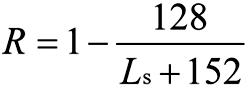
.2. In the case of cargo ships not less than 80 m in length (Ls ) and not greater than 100 m in length (Ls ):
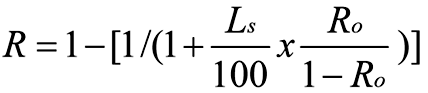
where Ro is the value R as calculated in accordance with the formula in subparagraph .1.
.3. In the case of passenger ships:
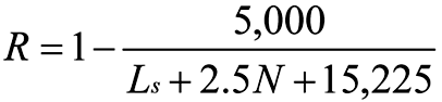
where:
N = N1 + 2N2
N1 = number of persons for whom lifeboats are provided
N2 = number of persons (including officers and crew) the ship is permitted to carry in excess of N1.
.4. Where the conditions of service are such that compliance with paragraph 2.3 of this regulation on the basis of N = N1 + 2N2 is impracticable and where the Administration considers that a suitably reduced degree of hazard exists, a lesser value of N may be taken but in no case less than N = N1 + N2.
1. The attained subdivision index A is obtained by the summation of the partial indices As, Ap and Al, (weighted as shown) calculated for the draughts ds, dp and dl defined in regulation 2 in accordance with the following formula:
A = 0.4As + 0.4Ap + 0.2Al
Each partial index is a summation of contributions from all damage cases taken in consideration, using the following formula:
A = Σpisi
where:
i represents each compartment or group of compartments under consideration,
pi accounts for the probability that only the compartment or group of compartments under consideration may be flooded, disregarding any horizontal subdivision, as defined in regulation 7-1,
si accounts for the probability of survival after flooding the compartment or group of compartments under consideration, and includes the effect of any horizontal subdivision, as defined in regulation 7-2.
2. In the calculation of A, the level trim shall be used for the deepest subdivision draught and the partial subdivision draught. The actual service trim shall be used for the light service draught. If in any service condition, the trim variation in comparison with the calculated trim is greater than 0.5% of Ls, one or more additional calculations of A are to be submitted for the same draughts but different trims so that, for all service conditions, the difference in trim in comparison with the reference trim used for one calculation will be less than 0.5% of Ls.
3. When determining the positive righting lever (GZ) of the residual stability curve, the displacement used should be that of the intact condition. That is, the constant displacement method of calculation should be used.
4. The summation indicated by the above formula shall be taken over the ship’s subdivision length (Ls) for all cases of flooding in which a single compartment or two or more adjacent compartments are involved. In the case of unsymmetrical arrangements, the calculated A value should be the mean value obtained from calculations involving both sides. Alternatively, it should be taken as that corresponding to the side which evidently gives the least favourable result.
5. Wherever wing compartments are fitted, contribution to the summation indicated by the formula shall be taken for all cases of flooding in which wing compartments are involved. Additionally, cases of simultaneous flooding of a wing compartment or group of compartments and the adjacent inboard compartment or group of compartments, but excluding damage of transverse extent greater than one half of the ship breadth B, may be added. For the purpose of this regulation, transverse extent is measured inboard from ship’s side, at right angle to the centreline at the level of the deepest subdivision draught.
6. In the flooding calculations carried out according to the regulations, only one breach of the hull and only one free surface need to be assumed. The assumed vertical extent of damage is to extend from the baseline upwards to any watertight horizontal subdivision above the waterline or higher. However, if a lesser extent of damage will give a more severe result, such extent is to be assumed.
7. If pipes, ducts or tunnels are situated within the assumed extent of damage, arrangements are to be made to ensure that progressive flooding cannot thereby extend to compartments other than those assumed flooded. However, the Administration may permit minor progressive flooding if it is demonstrated that its effects can be easily controlled and the safety of the ship is not impaired.
1. The factor pi for a compartment or group of compartments shall be calculated in accordance with paragraphs 1.1 and 1.2 using the following notations:
j = the aftmost damage zone number involved in the damage starting with No.1 at the stern;
n = the number of adjacent damage zones involved in the damage;
k = is the number of a particular longitudinal bulkhead as barrier for transverse penetration in a damage zone counted from shell towards the centre line. The shell has k = 0;
x1 = the distance from the aft terminal of Ls to the aft end of the zone in question;
x2 = the distance from the aft terminal of Ls to the forward end of the zone in question;
b = the mean transverse distance in metres measured at right angles to the centreline at the deepest subdivision loadline between the shell and an assumed vertical plane extended between the longitudinal limits used in calculating the factor pi and which is a tangent to, or common with, all or part of the outermost portion of the longitudinal bulkhead under consideration. This vertical plane shall be so orientated that the mean transverse distance to the shell is a maximum, but not more than twice the least distance between the plane and the shell. If the upper part of a longitudinal bulkhead is below the deepest subdivision loadline the vertical plane used for determination of b is assumed to extend upwards to the deepest subdivision waterline. In any case, b is not to be taken greater than B/2.
If the damage involves a single zone only:

If the damage involves two adjacent zones:
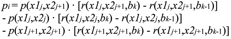
If the damage involves three or more adjacent zones:

and where r(x1, x2, b0 ) = 0
1.1. The factor p(x1, x2) is to be calculated according to the following formulae:
Overall normalized max damage length: Jmax = 10/33
Knuckle point in the distribution: Jkn = 5/33
Cumulative probability at Jkn : pk = 11/12
Maximum absolute damage length: lmax = 60 m
Length where normalized distribution ends: L* = 260 m
Probability density at J = 0:
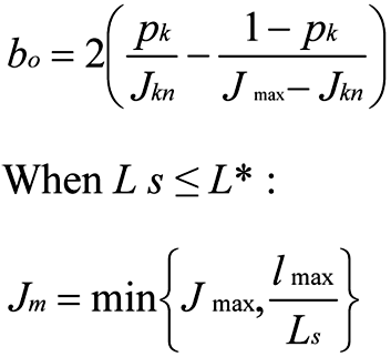
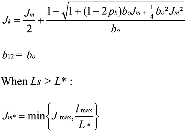
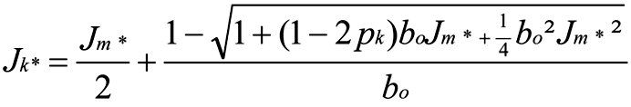
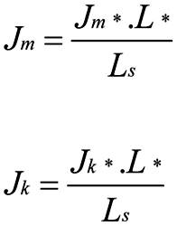
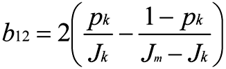
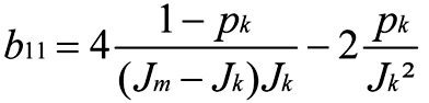
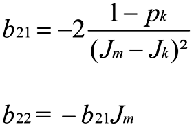
The non-dimensional damage length:
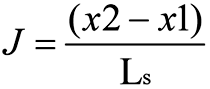
The normalized length of a compartment or group of compartments:
Jn is to be taken as the lesser of J and Jm
1.1.1. Where neither limits of the compartment or group of compartments under consideration coincides with the aft or forward terminals:
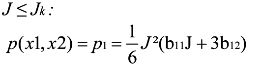
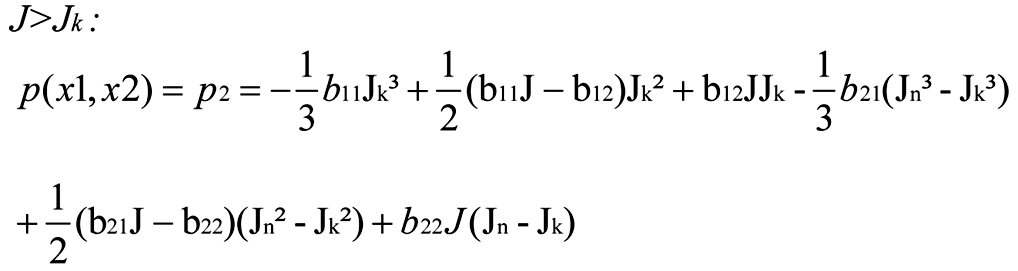
1.1.2. Where the aft limit of the compartment or group of compartments under consideration coincides with the aft terminal or the forward limit of the compartment or group of compartments under consideration coincides with the forward terminal:
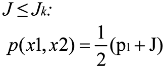
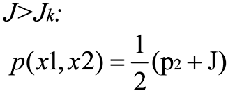
1.1.3. Where the compartment or groups of compartments considered extends over the entire subdivision length (Ls ):
1.2. The factor r(x1, x2, b) shall be determined by the following formulae:
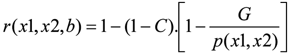
where:
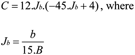
1.2.1. Where the compartment or groups of compartments considered extends over the entire subdivision length (Ls ):
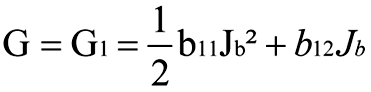
1.2.2. Where neither limits of the compartment or group of compartments under consideration coincides with the aft or forward terminals:
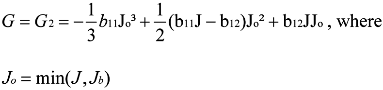
1.2.3. Where the aft limit of the compartment or group of compartments under consideration coincides with the aft terminal or the forward limit of the compartment or group of compartments under consideration coincides with the forward terminal:
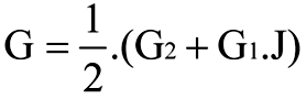
1. The factor si shall be determined for each case of assumed flooding, involving a compartment or group of compartments, in accordance with the following notations and the provisions in this regulation.
θe is the equilibrium heel angle in any stage of flooding, in degrees;
θv is the angle, in any stage of flooding, where the righting lever becomes negative, or the angle at which an opening incapable of being closed weathertight becomes submerged;
GZmax is the maximum positive righting lever, in metres, up to the angle θ v;
Range is the range of positive righting levers, in degrees, measured from the angle θ e. The positive range is to be taken up to the angle θ v;
Flooding stage is any discrete step during the flooding process, including the stage before equalization (if any) until final equilibrium has been reached.
1.1. The factor si , for any damage case at any initial loading condition, di , shall be obtained from the formula:

where:
sintermediate,i is the probability to survive all intermediate flooding stages until the final equilibrium stage, and is calculated in accordance with paragraph 2;
sfinal,i is the probability to survive in the final equilibrium stage of flooding. It is calculated in accordance with paragraph 3;
smom,i is the probability to survive heeling moments, and is calculated in accordance with paragraph 4.
2. The factor sintermediate,i is applicable only to passenger ships (for cargo ships sintermediate,i should be taken as unity) and shall be taken as the least of the s-factors obtained from all flooding stages including the stage before equalization, if any, and is to be calculated as follows:

where GZmax is not to be taken as more than 0.05 m and Range as not more than 7°.
sintermediate = 0, if the intermediate heel angle exceeds 15º. Where cross-flooding fittings are required, the time for equalization shall not exceed 10 min.
3. The factor sfinal,i shall be obtained from the formula:
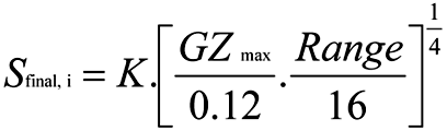
where:
GZmax is not to be taken as more than 0.12 m;
Range is not to be taken as more than 16°;
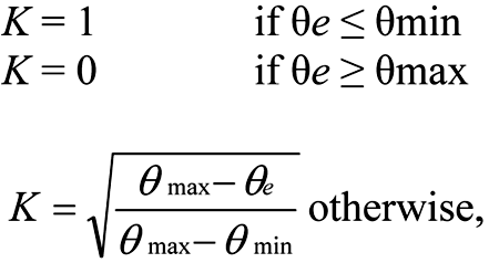
where:
θmin is 7° for passenger ships and 25° for cargo ships; and
θmax is 15° for passenger ships and 30° for cargo ships.
4. The factor smom,i is applicable only to passenger ships (for cargo ships smom,i shall be taken as unity) and shall be calculated at the final equilibrium from the formula:
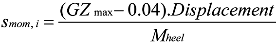
where:
Displacement is the intact displacement at the subdivision draught;
Mheel is the maximum assumed heeling moment as calculated in accordance with subparagraph 4.1; and

4.1. The heeling moment Mheel is to be calculated as follows:

4.1.1 Mpassenger is the maximum assumed heeling moment resulting from movement of passengers, and is to be obtained as follows:
Mpassenger = (0.075 · Np) · (0.45 · B) (tm)
where:
Np is the maximum number of passengers permitted to be on board in the service condition corresponding to the deepest subdivision draught under consideration; and
B is the beam of the ship.
Alternatively, the heeling moment may be calculated assuming the passengers are distributed with 4 persons per square metre on available deck areas towards one side of the ship on the decks where muster stations are located and in such a way that they produce the most adverse heeling moment. In doing so, a weight of 75 kg per passenger is to be assumed.
4.1.2. Mwind is the maximum assumed wind force acting in a damage situation:
Mwind = (P · A · Z) / 9,806 (tm)
where:
P = 120 N/m2;
A = projected lateral area above waterline;
Z = distance from centre of lateral projected area above waterline to T/2; and
T = ship’s draught, di .
4.1.3. MSurvivalcraft is the maximum assumed heeling moment due to the launching of all fully loaded davit-launched survival craft on one side of the ship. It shall be calculated using the following assumptions:
.1. all lifeboats and rescue boats fitted on the side to which the ship has heeled after having sustained damage shall be assumed to be swung out fully loaded and ready for lowering;
.2. for lifeboats which are arranged to be launched fully loaded from the stowed position, the maximum heeling moment during launching shall be taken;
.3. a fully loaded davit-launched liferaft attached to each davit on the side to which the ship has heeled after having sustained damage shall be assumed to be swung out ready for lowering;
.4. persons not in the life-saving appliances which are swung out shall not provide either additional heeling or righting moment; and
.5. life-saving appliances on the side of the ship opposite to the side to which the ship has heeled shall be assumed to be in a stowed position.
5. Unsymmetrical flooding is to be kept to a minimum consistent with the efficient arrangements. Where it is necessary to correct large angles of heel, the means adopted shall, where practicable, be self-acting, but in any case where controls to equalization devices are provided they shall be operable from above the bulkhead deck. These fittings together with their controls shall be acceptable to the Administration.5) Suitable information concerning the use of equalization devices shall be supplied to the master of the ship.
5.1. Tanks and compartments taking part in such equalization shall be fitted with air pipes or equivalent means of sufficient cross-section to ensure that the flow of water into the equalization compartments is not delayed.
5.2. In all cases, si is to be taken as zero in those cases where the final waterline, taking into account sinkage, heel and trim, immerses:
.1. the lower edge of openings through which progressive flooding may take place and such flooding is not accounted for in the calculation of factor si. Such openings shall include air-pipes, ventilators and openings which are closed by means of weathertight doors or hatch covers; and
.2. any part of the bulkhead deck in passenger ships considered a horizontal evacuation route for compliance with chapter II-2.
5.3. The factor si is to be taken as zero if, taking into account sinkage, heel and trim, any of the following occur in any intermediate stage or in the final stage of flooding:
.1. immersion of any vertical escape hatch in the bulkhead deck intended for compliance with chapter II-2;
.2. any controls intended for the operation of watertight doors, equalization devices, valves on piping or on ventilation ducts intended to maintain the integrity of watertight bulkheads from above the bulkhead deck become inaccessible or inoperable;
.3. immersion of any part of piping or ventilation ducts carried through a watertight boundary that is located within any compartment included in damage cases contributing to the attained index A, if not fitted with watertight means of closure at each boundary.
5.4. However, where compartments assumed flooded due to progressive flooding are taken into account in the damage stability calculations multiple values of sintermediate,i may be calculated assuming equalization in additional flooding phases.
5.5. Except as provided in paragraph 5.3.1, openings closed by means of watertight manhole covers and flush scuttles, small watertight hatch covers, remotely operated sliding watertight doors, side scuttles of the non-opening type as well as watertight access doors and hatch covers required to be kept closed at sea need not be considered.
6. Where horizontal watertight boundaries are fitted above the waterline under consideration the s-value calculated for the lower compartment or group of compartments shall be obtained by multiplying the value as determined in paragraph 1.1 by the reduction factor vm according to paragraph 6.1, which represents the probability that the spaces above the horizontal subdivision will not be flooded.
6.1. The factor vm shall be obtained from the formula:
vm = v(Hj, n, m, d) – v(Hj, n, m-1,d)
where:
Hj, n, m is the least height above the baseline, in metres, within the longitudinal range of x1()…x2(+-1) of the mth horizontal boundary which is assumed to limit the vertical extent of flooding for the damaged compartments under consideration;
Hj, n, m-1 is the least height above the baseline, in metres, within the longitudinal range of x1()…x2(+-1) of the (m-1)th horizontal boundary which is assumed to limit the vertical extent of flooding for the damaged compartments under consideration;
j signifies the aft terminal of the damaged compartments under consideration;
m represents each horizontal boundary counted upwards from the waterline under consideration;
d is the draught in question as defined in regulation 2; and
x1 and x2 represent the terminals of the compartment or group of compartments considered in regulation 7-1.
6.1.1. The factors v(Hj, n, m, d) and v(Hj, n, m-1, d) shall be obtained from the formulae:

where:
v(Hj, n, m, d) is to be taken as 1, if Hm coincides with the uppermost watertight boundary of the ship within the range (x1()…x2(+-1)), and
v(Hj, n, 0, d) is to be taken as 0.
In no case is vm to be taken as less than zero or more than 1.
6.2. In general, each contribution dA to the index A in the case of horizontal subdivisions is obtained from the formula:

where:
vm = the v-value calculated in accordance with paragraph 6.1;
smin = the least s-factor for all combinations of damages obtained when the assumed damage extends from the assumed damage height Hm downwards.
1. For the purpose of the subdivision and damage stability calculations of the regulations, the permeability of each general compartment or part of a compartment shall be as follows:
Spaces | Permeability |
|---|---|
Appropriated to stores Occupied by accommodation Occupied by machinery Void spaces Intended for liquids | 0.60 0.95 0.85 0.95 0 or 0.951) |
2. For the purpose of the subdivision and damage stability calculations of the regulations, the permeability of each cargo compartment or part of a compartment shall be as follows:
Spaces | Permeability at draught ds | Permeability at draught dp | Permeability at draught dl |
|---|---|---|---|
Dry cargo spaces Container spaces Ro-ro spaces Cargo liquids | 0.70 0.70 0.90 0.70 | 0.80 0.80 0.90 0.80 | 0.95 0.95 0.95 0.95 |
3. Other figures for permeability may be used if substantiated by calculations.
1. A passenger ship intended to carry 400 or more persons shall have watertight subdivision abaft the collision bulkhead so that si = 1 for the three loading conditions on which is based the calculation of the subdivision index and for a damage involving all the compartments within 0.08L measured from the forward perpendicular.
2. A passenger ship intended to carry 36 or more persons is to be capable of withstanding damage along the side shell to an extent specified in paragraph 3.
Compliance with this regulation is to be achieved by demonstrating that si , as defined in regulation 7-2, is not less than 0.9 for the three loading conditions on which is based the calculation of the subdivision index.
3. The damage extent to be assumed when demonstrating compliance with paragraph 2, is to be dependent on both N as defined in regulation 6, and Ls as defined in regulation 2, such that:
.1. the vertical extent of damage is to extend from the ship’s moulded baseline to a position up to 12.5 m above the position of the deepest subdivision draught as defined in regulation 2, unless a lesser vertical extent of damage were to give a lower value of si , in which case this reduced extent is to be used;
.2. where 400 or more persons are to be carried, a damage length of 0.03Ls but not less than 3 m is to be assumed at any position along the side shell, in conjunction with a penetration inboard of 0.1B but not less than 0.75 m measured inboard from the ship side, at right angle to the centreline at the level of the deepest subdivision draught;
.3. where less than 400 persons are carried, damage length is to be assumed at any position along the shell side between transverse watertight bulkheads provided that the distance between two adjacent transverse watertight bulkheads is not less than the assumed damage length. If the distance between adjacent transverse watertight bulkheads is less than the assumed damage length, only one of these bulkheads shall be considered effective for the purpose of demonstrating compliance with paragraph 2;
.4. where 36 persons are carried, a damage length of 0.015Ls but not less than 3 m is to be assumed, in conjunction with a penetration inboard of 0.05B but not less than 0.75 m; and
.5. where more than 36, but fewer than 400 persons are carried the values of damage length and penetration inboard, used in the determination of the assumed extent of damage, are to be obtained by linear interpolation between the values of damage length and penetration which apply for ships carrying 36 persons and 400 persons as specified in subparagraphs .4 and .2.
1. Application
This regulation applies to passenger ships constructed on or after 1 July 2010 to which regulation II-2/21 applies.
2. Availability of essential systems in case of flooding damage6)
A passenger ship shall be designed so that the systems specified in regulation II-2/21.4 remain operational when the ship is subject to flooding of any single watertight compartment.
1. A double bottom shall be fitted extending from the collision bulkhead to the afterpeak bulkhead, as far as this is practicable and compatible with the design and proper working of the ship.
2. Where a double bottom is required to be fitted the inner bottom shall be continued out to the ship’s sides in such a manner as to protect the bottom to the turn of the bilge.
Such protection will be deemed satisfactory if the inner bottom is not lower at any part than a plane parallel with the keel line and which is located not less than a vertical distance h measured from the keel line, as calculated by the formula:
h = B/20
However, in no case is the value of h to be less than 760 mm, and need not be taken as more than 2,000 mm.
3. Small wells constructed in the double bottom in connection with drainage arrangements of holds, etc., shall not extend downward more than necessary. A well extending to the outer bottom is, however, permitted at the after end of the shaft tunnel.
Other wells (e.g., for lubricating oil under main engines) may be permitted by the Administration if satisfied that the arrangements give protection equivalent to that afforded by a double bottom complying with this regulation. In no case shall the vertical distance from the bottom of such a well to a plane coinciding with the keel line be less than 500 mm.
4. A double bottom need not be fitted in way of watertight tanks, including dry tanks of moderate size, provided the safety of the ship is not impaired in the event of bottom or side damage.
5. In the case of passenger ships to which the provisions of regulation 1.5 apply and which are engaged on regular service within the limits of a short international voyage as defined in regulation III/3.22, the Administration may permit a double bottom to be dispensed with if satisfied that the fitting of a double bottom in that part would not be compatible with the design and proper working of the ship.
6. Any part of a passenger ship or a cargo ship that is not fitted with a double bottom in accordance with paragraphs 1, 4 or 5 shall be capable of withstanding bottom damages, as specified in paragraph 8, in that part of the ship.
7. In the case of unusual bottom arrangements in a passenger ship or a cargo ship, it shall be demonstrated that the ship is capable of withstanding bottom damages as specified in paragraph 8.
8. Compliance with paragraphs 6 or 7 is to be achieved by demonstrating that si , when calculated in accordance with regulation 7-2, is not less than 1 for all service conditions when subject to a bottom damage assumed at any position along the ship’s bottom and with an extent specified in subparagraph .2 below for the affected part of the ship:
.1. Flooding of such spaces shall not render emergency power and lighting, internal communication, signals or other emergency devices inoperable in other parts of the ship.
.2. Assumed extent of damage shall be as follows:
For 0.3 L from the forward perpendicular of the ship | Any other part of the ship | |
Longitudinal extent | 1/3 L2/3 or 14.5 m, whichever is less | 1/3 L2/3 or 14.5 m, whichever is less |
Transverse extent | B/6 or 10 m, whichever is less | B/6 or 5 m, whichever is less |
Vertical extent, measured from the keel line | B/20 or 2 m, whichever is less | B/20 or 2 m, whichever is less |
.3. If any damage of a lesser extent than the maximum damage specified in subparagraph .2 would result in a more severe condition, such damage should be considered.
9. In case of large lower holds in passenger ships, the Administration may require an increased double bottom height of not more than B/10 or 3 m, whichever is less, measured from the keel line. Alternatively, bottom damages may be calculated for these areas, in accordance with paragraph 8, but assuming an increased vertical extent.
1. Each watertight subdivision bulkhead, whether transverse or longitudinal, shall be constructed having scantlings as specified in regulation 2.17. In all cases, watertight subdivision bulkheads shall be capable of supporting at least the pressure due to a head of water up to the bulkhead deck.
2. Steps and recesses in watertight bulkheads shall be as strong as the bulkhead at the place where each occurs.
1. Testing watertight spaces not intended to hold liquids and cargo holds intended to hold ballast by filling them with water is not compulsory. When testing by filling with water is not carried out, a hose test shall be carried out where practicable. This test shall be carried out in the most advanced stage of the fitting out of the ship. Where a hose test is not practicable because of possible damage to machinery, electrical equipment insulation or outfitting items, it may be replaced by a careful visual examination of welded connections, supported where deemed necessary by means such as a dye penetrant test or an ultrasonic leak test or an equivalent test. In any case a thorough inspection of the watertight bulkheads shall be carried out.
2. The forepeak, double bottom (including duct keels) and inner skins shall be tested with water to a head corresponding to the requirements of regulation 10.1.
3. Tanks which are intended to hold liquids, and which form part of the watertight subdivision of the ship, shall be tested for tightness and structural strength with water to a head corresponding to its design pressure. The water head is in no case to be less than the top of the air pipes or to a level of 2.4 m above the top of the tank, whichever is the greater.
4. The tests referred to in paragraphs 2 and 3 are for the purpose of ensuring that the subdivision structural arrangements are watertight and are not to be regarded as a test of the fitness of any compartment for the storage of oil fuel or for other special purposes for which a test of a superior character may be required depending on the height to which the liquid has access in the tank or its connections.
1. A collision bulkhead shall be fitted which shall be watertight up to the bulkhead deck. This bulkhead shall be located at a distance from the forward perpendicular of not less than 0.05L or 10 m, whichever is the less, and, except as may be permitted by the Administration, not more than 0.08L or 0.05L + 3 m, whichever is the greater.
2. Where any part of the ship below the waterline extends forward of the forward perpendicular, e.g., a bulbous bow, the distances stipulated in paragraph 1 shall be measured from a point either:
.1. at the mid-length of such extension;
.2. at a distance 0.015L forward of the forward perpendicular; or
.3. at a distance 3 m forward of the forward perpendicular, whichever gives the smallest measurement.
3. The bulkhead may have steps or recesses provided they are within the limits prescribed in paragraph 1 or 2.
4. No doors, manholes, access openings, ventilation ducts or any other openings shall be fitted in the collision bulkhead below the bulkhead deck.
5.1. Except as provided in paragraph 5.2, the collision bulkhead may be pierced below the bulkhead deck by not more than one pipe for dealing with fluid in the forepeak tank, provided that the pipe is fitted with a screw-down valve capable of being operated from above the bulkhead deck, the valve chest being secured inside the forepeak to the collision bulkhead. The Administration may, however, authorize the fitting of this valve on the after side of the collision bulkhead provided that the valve is readily accessible under all service conditions and the space in which it is located is not a cargo space. All valves shall be of steel, bronze or other approved ductile material. Valves of ordinary cast iron or similar material are not acceptable.
5.2. If the forepeak is divided to hold two different kinds of liquids the Administration may allow the collision bulkhead to be pierced below the bulkhead deck by two pipes, each of which is fitted as required by paragraph 5.1, provided the Administration is satisfied that there is no practical alternative to the fitting of such a second pipe and that, having regard to the additional subdivision provided in the forepeak, the safety of the ship is maintained.
6. Where a long forward superstructure is fitted the collision bulkhead shall be extended weathertight to the deck next above the bulkhead deck. The extension need not be fitted directly above the bulkhead below provided it is located within the limits prescribed in paragraph 1 or 2 with the exception permitted by paragraph 7 and that the part of the deck which forms the step is made effectively weathertight. The extension shall be so arranged as to preclude the possibility of the bow door causing damage to it in the case of damage to, or detachment of, a bow door.
7. Where bow doors are fitted and a sloping loading ramp forms part of the extension of the collision bulkhead above the bulkhead deck the ramp shall be weathertight over its complete length. In cargo ships the part of the ramp which is more than 2.3 m above the bulkhead deck may extend forward of the limit specified in paragraph 1 or 2. Ramps not meeting the above requirements shall be disregarded as an extension of the collision bulkhead.
8. The number of openings in the extension of the collision bulkhead above the freeboard deck shall be restricted to the minimum compatible with the design and normal operation of the ship. All such openings shall be capable of being closed weathertight.
9. Bulkheads shall be fitted separating the machinery space from cargo and accommodation spaces forward and aft and made watertight up to the bulkhead deck. In passenger ships an afterpeak bulkhead shall also be fitted and made watertight up to the bulkhead deck. The afterpeak bulkhead may, however, be stepped below the bulkhead deck, provided the degree of safety of the ship as regards subdivision is not thereby diminished.
10. In all cases stern tubes shall be enclosed in watertight spaces of moderate volume.
In passenger ships the stern gland shall be situated in a watertight shaft tunnel or other watertight space separate from the stern tube compartment and of such volume that, if flooded by leakage through the stern gland, the bulkhead deck will not be immersed. In cargo ships other measures to minimize the danger of water penetrating into the ship in case of damage to stern tube arrangements may be taken at the discretion of the Administration.
1. The number of openings in watertight bulkheads shall be reduced to the minimum compatible with the design and proper working of the ship, satisfactory means shall be provided for closing these openings.
2.1. Where pipes, scuppers, electric cables, etc., are carried through watertight bulkheads, arrangements shall be made to ensure the watertight integrity of the bulkheads.
2.2. Valves not forming part of a piping system shall not be permitted in watertight bulkheads.
2.3. Lead or other heat sensitive materials shall not be used in systems which penetrate watertight bulkheads, where deterioration of such systems in the event of fire would impair the watertight integrity of the bulkheads.
3. No doors, manholes, or access openings are permitted in watertight transverse bulkheads dividing a cargo space from an adjoining cargo space, except as provided in paragraph 9.1 and in regulation 14.
4. Subject to paragraph 10, not more than one door, apart from the doors to shaft tunnels, may be fitted in each watertight bulkhead within spaces containing the main and auxiliary propulsion machinery including boilers serving the needs of propulsion. Where two or more shafts are fitted, the tunnels shall be connected by an intercommunicating passage. There shall be only one door between the machinery space and the tunnel spaces where two shafts are fitted and only two doors where there are more than two shafts. All these doors shall be of the sliding type and shall be so located as to have their sills as high as practicable. The hand gear for operating these doors from above the bulkhead deck shall be situated outside the spaces containing the machinery.
5.1. Watertight doors, except as provided in paragraph 9.1 or regulation 14, shall be power-operated sliding doors complying with the requirements of paragraph 7 capable of being closed simultaneously from the central operating console at the navigation bridge in not more than 60 s with the ship in the upright position.
5.2. The means of operation whether by power or by hand of any power-operated sliding watertight door shall be capable of closing the door with the ship listed to 15°. either way. Consideration shall also be given to the forces which may act on either side of the door as may be experienced when water is flowing through the opening applying a static head equivalent to a water height of at least 1 m above the sill on the centreline of the door.
5.3. Watertight door controls, including hydraulic piping and electric cables, shall be kept as close as practicable to the bulkhead in which the doors are fitted, in order to minimize the likelihood of them being involved in any damage which the ship may sustain. The positioning of watertight doors and their controls shall be such that if the ship sustains damage within one fifth of the breadth of the ship, as defined in regulation 2, such distance being measured at right angles to the centreline at the level of the deepest subdivision draught, the operation of the watertight doors clear of the damaged portion of the ship is not impaired.
6. All power-operated sliding watertight doors shall be provided with means of indication which will show at all remote operating positions whether the doors are open or closed. Remote operating positions shall only be at the navigation bridge as required by paragraph 7.1.5 and at the location where hand operation above the bulkhead deck is required by paragraph 7.1.4.
7.1. Each power-operated sliding watertight door:
.1. shall have a vertical or horizontal motion;
.2. shall, subject to paragraph 10, be normally limited to a maximum clear opening width of 1.2 m. The Administration may permit larger doors only to the extent considered necessary for the effective operation of the ship provided that other safety measures, including the following, are taken into consideration:
.1. special consideration shall be given to the strength of the door and its closing appliances in order to prevent leakages; and
.2. the door shall be located inboard the damage zone B/5;
.3. shall be fitted with the necessary equipment to open and close the door using electric power, hydraulic power, or any other form of power that is acceptable to the Administration;
.4. shall be provided with an individual hand-operated mechanism. It shall be possible to open and close the door by hand at the door itself from either side, and in addition, close the door from an accessible position above the bulkhead deck with an all round crank motion or some other movement providing the same degree of safety acceptable to the Administration.
Direction of rotation or other movement is to be clearly indicated at all operating positions. The time necessary for the complete closure of the door, when operating by hand gear, shall not exceed 90 s with the ship in the upright position;
.5. shall be provided with controls for opening and closing the door by power from both sides of the door and also for closing the door by power from the central operating console at the navigation bridge;
.6. shall be provided with an audible alarm, distinct from any other alarm in the area, which will sound whenever the door is closed remotely by power and which shall sound for at least 5 s but no more than 10 s before the door begins to move and shall continue sounding until the door is completely closed. In the case of remote hand operation it is sufficient for the audible alarm to sound only when the door is moving. Additionally, in passenger areas and areas of high ambient noise the Administration may require the audible alarm to be supplemented by an intermittent visual signal at the door; and
.7. shall have an approximately uniform rate of closure under power. The closure time, from the time the door begins to move to the time it reaches the completely closed position shall in no case be less than 20 s or more than 40 s with the ship in the upright position.
7.2. The electrical power required for power-operated sliding watertight doors shall be supplied from the emergency switchboard either directly or by a dedicated distribution board situated above the bulkhead deck. The associated control, indication and alarm circuits shall be supplied from the emergency switchboard either directly or by a dedicated distribution board situated above the bulkhead deck and be capable of being automatically supplied by the transitional source of emergency electrical power required by regulation 42.3.1.3 in the event of failure of either the main or emergency source of electrical power.
7.3. Power-operated sliding watertight doors shall have either:
.1. a centralized hydraulic system with two independent power sources each consisting of a motor and pump capable of simultaneously closing all doors. In addition, there shall be for the whole installation hydraulic accumulators of sufficient capacity to operate all the doors at least three times, i.e. closed-open-closed, against an adverse list of 15º. This operating cycle shall be capable of being carried out when the accumulator is at the pump cut-in pressure. The fluid used shall be chosen considering the temperatures liable to be encountered by the installation during its service. The power operating system shall be designed to minimize the possibility of having a single failure in the hydraulic piping adversely affect the operation of more than one door. The hydraulic system shall be provided with a low-level alarm for hydraulic fluid reservoirs serving the power-operated system and a low gas pressure alarm or other effective means of monitoring loss of stored energy in hydraulic accumulators.
These alarms are to be audible and visual and shall be situated on the central operating console at the navigation bridge; or
.2. an independent hydraulic system for each door with each power source consisting of a motor and pump capable of opening and closing the door.
In addition, there shall be a hydraulic accumulator of sufficient capacity to operate the door at least three times, i.e. closed-open-closed, against an adverse list of 15°. This operating cycle shall be capable of being carried out when the accumulator is at the pump cut-in pressure. The fluid used shall be chosen considering the temperatures liable to be encountered by the installation during its service. A low gas pressure group alarm or other effective means of monitoring loss of stored energy in hydraulic accumulators shall be provided at the central operating console on the navigation bridge. Loss of stored energy indication at each local operating position shall also be provided; or
.3. an independent electrical system and motor for each door with each power source consisting of a motor capable of opening and closing the door. The power source shall be capable of being automatically supplied by the transitional source of emergency electrical power as required by regulation 42.4.2 – in the event of failure of either the main or emergency source of electrical power and with sufficient capacity to operate the door at least three times, i.e. closed-open-closed, against an adverse list of 15°.
For the systems specified in paragraphs 7.3.1, 7.3.2 and 7.3.3, provision should be made as follows: Power systems for power-operated watertight sliding doors shall be separate from any other power system. A single failure in the electric or hydraulic power-operated systems excluding the hydraulic actuator shall not prevent the hand operation of any door.
7.4. Control handles shall be provided at each side of the bulkhead at a minimum height of 1.6 m above the floor and shall be so arranged as to enable persons passing through the doorway to hold both handles in the open position without being able to set the power closing mechanism in operation accidentally. The direction of movement of the handles in opening and closing the door shall be in the direction of door movement and shall be clearly indicated.
7.5. As far as practicable, electrical equipment and components for watertight doors shall be situated above the bulkhead deck and outside hazardous areas and spaces.
7.6. The enclosures of electrical components necessarily situated below the bulkhead deck shall provide suitable protection against the ingress of water.7)
7.7. Electric power, control, indication and alarm circuits shall be protected against fault in such a way that a failure in one door circuit will not cause a failure in any other door circuit. Short circuits or other faults in the alarm or indicator circuits of a door shall not result in a loss of power operation of that door. Arrangements shall be such that leakage of water into the electrical equipment located below the bulkhead deck will not cause the door to open.
7.8. A single electrical failure in the power operating or control system of a power-operated sliding watertight door shall not result in a closed door opening.
Availability of the power supply should be continuously monitored at a point in the electrical circuit as near as practicable to each of the motors required by paragraph 7.3.
Loss of any such power supply should activate an audible and visual alarm at the central operating console at the navigation bridge.
8.1. The central operating console at the navigation bridge shall have a “master mode” switch with two modes of control: a “local control” mode which shall allow any door to be locally opened and locally closed after use without automatic closure, and a “doors closed” mode which shall automatically close any door that is open. The “doors closed” mode shall automatically close any door that is open. The “doors closed” mode shall permit doors to be opened locally and shall automatically re-close the doors upon release of the local control mechanism. The “master mode” switch shall normally be in the “local control” mode. The “doors closed” mode shall only be used in an emergency or for testing purposes. Special consideration shall be given to the reliability of the “master mode” switch.
8.2. The central operating console at the navigation bridge shall be provided with a diagram showing the location of each door, with visual indicators to show whether each door is open or closed. A red light shall indicate a door is fully open and a green light shall indicate a door is fully closed. When the door is closed remotely the red light shall indicate the intermediate position by flashing. The indicating circuit shall be independent of the control circuit for each door.
8.3. It shall not be possible to remotely open any door from the central operating console.
9.1. If the Administration is satisfied that such doors are essential, watertight doors of satisfactory construction may be fitted in watertight bulkheads dividing cargo between deck spaces. Such doors may be hinged, rolling or sliding doors but shall not be remotely controlled. They shall be fitted at the highest level and as far from the shell plating as practicable, but in no case shall the outboard vertical edges be situated at a distance from the shell plating which is less than one fifth of the breadth of the ship, as defined in regulation 2, such distance being measured at right angles to the centreline at the level of the deepest subdivision draught.
9.2. Should any such doors be accessible during the voyage, they shall be fitted with a device which prevents unauthorized opening. When it is proposed to fit such doors, the number and arrangements shall receive the special consideration of the Administration.
10. Portable plates on bulkheads shall not be permitted except in machinery spaces.
The Administration may permit not more than one power-operated sliding watertight door in each watertight bulkhead larger than those specified in paragraph 7.1.2 to be substituted for these portable plates, provided these doors are intended to remain closed during navigation except in case of urgent necessity at the discretion of the master. These doors need not meet the requirements of paragraph 7.1.4 regarding complete closure by hand-operated gear in 90 s.
11.1. Where trunkways or tunnels for access from crew accommodation to the stokehold, for piping, or for any other purpose are carried through watertight bulkheads, they shall be watertight and in accordance with the requirements of regulation 16-1. The access to at least one end of each such tunnel or trunkway, if used as a passage at sea, shall be through a trunk extending watertight to a height sufficient to permit access above the bulkhead deck. The access to the other end of the trunkway or tunnel may be through a watertight door of the type required by its location in the ship. Such trunkways or tunnels shall not extend through the first subdivision bulkhead abaft the collision bulkhead.
11.2. Where it is proposed to fit tunnels piercing watertight bulkheads, these shall receive the special consideration of the Administration.
11.3. Where trunkways in connection with refrigerated cargo and ventilation or forced draught trunks are carried through more than one watertight bulkhead, the means of closure at such openings shall be operated by power and be capable of being closed from a central position situated above the bulkhead deck.
1. The number of openings in watertight subdivisions is to be kept to a minimum compatible with the design and proper working of the ship. Where penetrations of watertight bulkheads and internal decks are necessary for access, piping, ventilation, electrical cables, etc., arrangements are to be made to maintain the watertight integrity.
The Administration may permit relaxation in the watertightness of openings above the freeboard deck, provided that it is demonstrated that any progressive flooding can be easily controlled and that the safety of the ship is not impaired.
2. Doors provided to ensure the watertight integrity of internal openings which are used while at sea are to be sliding watertight doors capable of being remotely closed from the bridge and are also to be operable locally from each side of the bulkhead. Indicators are to be provided at the control position showing whether the doors are open or closed, and an audible alarm is to be provided at the door closure. The power, control and indicators are to be operable in the event of main power failure. Particular attention is to be paid to minimizing the effect of control system failure. Each power-operated sliding watertight door shall be provided with an individual hand-operated mechanism. It shall be possible to open and close the door by hand at the door itself from both sides.
3. Access doors and access hatch covers normally closed at sea, intended to ensure the watertight integrity of internal openings, shall be provided with means of indication locally and on the bridge showing whether these doors or hatch covers are open or closed.
A notice is to be affixed to each such door or hatch cover to the effect that it is not to be left open.
4. Watertight doors or ramps of satisfactory construction may be fitted to internally subdivide large cargo spaces, provided that the Administration is satisfied that such doors or ramps are essential. These doors or ramps may be hinged, rolling or sliding doors or ramps, but shall not be remotely controlled.8) Should any of the doors or ramps be accessible during the voyage, they shall be fitted with a device which prevents unauthorized opening.
5. Other closing appliances which are kept permanently closed at sea to ensure the watertight integrity of internal openings shall be provided with a notice which is to be affixed to each such closing appliance to the effect that it is to be kept closed. Manholes fitted with closely bolted covers need not be so marked.
1. This regulation applies to passenger ships designed or adapted for the carriage of goods vehicles and accompanying personnel.
2. If in such a ship the total number of passengers which include personnel accompanying vehicles does not exceed 12 + Ad /25, where Ad = total deck area (square metres) of spaces available for the stowage of goods vehicles and where the clear height at the stowage position and at the entrance to such spaces is not less than 4 m, the provisions of regulations 13.9.1 and 13.9.2 in respect of watertight doors apply except that the doors may be fitted at any level in watertight bulkheads dividing cargo spaces.
Additionally, indicators are required on the navigation bridge to show automatically when each door is closed and all door fastenings are secured.
3. The ship may not be certified for a higher number of passengers than assumed in paragraph 2, if a watertight door has been fitted in accordance with this regulation.
1. The number of openings in the shell plating shall be reduced to the minimum compatible with the design and proper working of the ship.
2. The arrangement and efficiency of the means for closing any opening in the shell plating shall be consistent with its intended purpose and the position in which it is fitted and generally to the satisfaction of the Administration.
3.1. Subject to the requirements of the International Convention on Load Lines in force, no sidescuttle shall be fitted in such a position that its sill is below a line drawn parallel to the bulkhead deck at side and having its lowest point 2.5% of the breadth of the ship above the deepest subdivision draught, or 500 mm, whichever is the greater.
3.2. All sidescuttles the sills of which are below the bulkhead deck of passenger ships and the freeboard deck of cargo ships, as permitted by paragraph 3.1, shall be of such construction as will effectively prevent any person opening them without the consent of the master of the ship.
4. Efficient hinged inside deadlights so arranged that they can be easily and effectively closed and secured watertight, shall be fitted to all sidescuttles except that abaft one eighth of the ship’s length from the forward perpendicular and above a line drawn parallel to the bulkhead deck at side and having its lowest point at a height of 3.7 m plus 2.5% of the breadth of the ship above the deepest subdivision draught, the deadlights may be portable in passenger accommodation other than that for steerage passengers, unless the deadlights are required by the International Convention on Load Lines in force to be permanently attached in their proper positions. Such portable deadlights shall be stowed adjacent to the sidescuttles they serve.
5.1. No sidescuttles shall be fitted in any spaces which are appropriated exclusively to the carriage of cargo or coal.
5.2. Sidescuttles may, however, be fitted in spaces appropriated alternatively to the carriage of cargo or passengers, but they shall be of such construction as will effectively prevent any person opening them or their deadlights without the consent of the master.
6. Automatic ventilating sidescuttles shall not be fitted in the shell plating below the bulkhead deck of passenger ships and the freeboard deck of cargo ships without the special sanction of the Administration.
7. The number of scuppers, sanitary discharges and other similar openings in the shell plating shall be reduced to the minimum either by making each discharge serve for as many as possible of the sanitary and other pipes, or in any other satisfactory manner.
8.1. All inlets and discharges in the shell plating shall be fitted with efficient and accessible arrangements for preventing the accidental admission of water into the ship.
8.2.1. Subject to the requirements of the International Convention on Load Lines in force, and except as provided in paragraph 8.3, each separate discharge led through the shell plating from spaces below the bulkhead deck of passenger ships and the freeboard deck of cargo ships shall be provided with either one automatic non-return valve fitted with a positive means of closing it from above the bulkhead deck or with two automatic non-return valves without positive means of closing, provided that the inboard valve is situated above the deepest subdivision draught and is always accessible for examination under service conditions. Where a valve with positive means of closing is fitted, the operating position above the bulkhead deck shall always be readily accessible and means shall be provided for indicating whether the valve is open or closed.
8.2.2. The requirements of the International Convention on Load Lines in force shall apply to discharges led through the shell plating from spaces above the bulkhead deck of passenger ships and the freeboard deck of cargo ships.
8.3. Machinery space, main and auxiliary sea inlets and discharges in connection with the operation of machinery shall be fitted with readily accessible valves between the pipes and the shell plating or between the pipes and fabricated boxes attached to the shell plating. In manned machinery spaces the valves may be controlled locally and shall be provided with indicators showing whether they are open or closed.
8.4. Moving parts penetrating the shell plating below the deepest subdivision draught shall be fitted with a watertight sealing arrangement acceptable to the Administration. The inboard gland shall be located within a watertight space of such volume that, if flooded, the bulkhead deck will not be submerged. The Administration may require that if such compartment is flooded, essential or emergency power and lighting, internal communication, signals or other emergency devices must remain available in other parts of the ship.
8.5. All shell fittings and valves required by this regulation shall be of steel, bronze or other approved ductile material. Valves of ordinary cast iron or similar material are not acceptable. All pipes to which this regulation refers shall be of steel or other equivalent material to the satisfaction of the Administration.
9. Gangway, cargo and fuelling ports fitted below the bulkhead deck of passenger ships and the freeboard deck of cargo ships shall be watertight and in no case be so fitted as to have their lowest point below the deepest subdivision draught.
10.1. The inboard opening of each ash-chute, rubbish-chute, etc., shall be fitted with an efficient cover.
10.2. If the inboard opening is situated below the bulkhead deck of passenger ships and the freeboard deck of cargo ships, the cover shall be watertight and, in addition, an automatic non-return valve shall be fitted in the chute in an easily accessible position above the deepest subdivision draught.
1. All external openings leading to compartments assumed intact in the damage analysis, which are below the final damage waterline, are required to be watertight.
2. External openings required to be watertight in accordance with paragraph 1 shall, except for cargo hatch covers, be fitted with indicators on the bridge.
3. Openings in the shell plating below the deck limiting the vertical extent of damage shall be fitted with a device that prevents unauthorized opening if they are accessible during the voyage.
4. Other closing appliances which are kept permanently closed at sea to ensure the watertight integrity of external openings shall be provided with a notice affixed to each appliance to the effect that it is to be kept closed. Manholes fitted with closely bolted covers need not be so marked.
1. In all ships:
.1. the design, materials and construction of all watertight doors, sidescuttles, gangway and cargo ports, valves, pipes, ash-chutes and rubbish-chutes referred to in these regulations shall be to the satisfaction of the Administration;
.2. such valves, doors and mechanisms shall be suitably marked to ensure that they may be properly used to provide maximum safety; and
.3. the frames of vertical watertight doors shall have no groove at the bottom in which dirt might lodge and prevent the door closing properly.
2. In passenger ships and cargo ships watertight doors shall be tested by water pressure to a head of water they might sustain in a final or intermediate stage of flooding.
Where testing of individual doors is not carried out because of possible damage to insulation or outfitting items, testing of individual doors may be replaced by a prototype pressure test of each type and size of door with a test pressure corresponding at least to the head required for the intended location. The prototype test shall be carried out before the door is fitted. The installation method and procedure for fitting the door on board shall correspond to that of the prototype test. When fitted on board, each door shall be checked for proper seating between the bulkhead, the frame and the door.
1. Watertight decks, trunks, tunnels, duct keels and ventilators shall be of the same strength as watertight bulkheads at corresponding levels. The means used for making them watertight, and the arrangements adopted for closing openings in them, shall be to the satisfaction of the Administration. Watertight ventilators and trunks shall be carried at least up to the bulkhead deck in passenger ships and up to the freeboard deck in cargo ships.
2. Where a ventilation trunk passing through a structure penetrates the bulkhead deck, the trunk shall be capable of withstanding the water pressure that may be present within the trunk, after having taken into account the maximum heel angle allowable during intermediate stages of flooding, in accordance with regulation 7-2.
3. Where all or part of the penetration of the bulkhead deck is on the main ro-ro deck, the trunk shall be capable of withstanding impact pressure due to internal water motions (sloshing) of water trapped on the ro-ro deck.
4. After completion, a hose or flooding test shall be applied to watertight decks and a hose test to watertight trunks, tunnels and ventilators.
1. The Administration may require that all reasonable and practicable measures shall be taken to limit the entry and spread of water above the bulkhead deck. Such measures may include partial bulkheads or webs. When partial watertight bulkheads and webs are fitted on the bulkhead deck, above or in the immediate vicinity of watertight bulkheads, they shall have watertight shell and bulkhead deck connections so as to restrict the flow of water along the deck when the ship is in a heeled damaged condition. Where the partial watertight bulkhead does not line up with the bulkhead below, the bulkhead deck between shall be made effectively watertight. Where openings, pipes, scuppers, electric cables etc. are carried through the partial watertight bulkheads or decks within the immersed part of the bulkhead deck, arrangements shall be made to ensure the watertight integrity of the structure above the bulkhead deck.9)
2. All openings in the exposed weather deck shall have coamings of ample height and strength and shall be provided with efficient means for expeditiously closing them weathertight. Freeing ports, open rails and scuppers shall be fitted as necessary for rapidly clearing the weather deck of water under all weather conditions.
3. The open end of air pipes terminating within a superstructure shall be at least 1 m above the waterline when the ship heels to an angle of 15º, or the maximum angle of heel during intermediate stages of flooding, as determined by direct calculation, whichever is the greater. Alternatively, air pipes from tanks other than oil tanks may discharge through the side of the superstructure. The provisions of this paragraph are without prejudice to the provisions of the International Convention on Load Lines in force.
4. Sidescuttles, gangway, cargo and fuelling ports and other means for closing openings in the shell plating above the bulkhead deck shall be of efficient design and construction and of sufficient strength having regard to the spaces in which they are fitted and their positions relative to the deepest subdivision draught.10)
5. Efficient inside deadlights, so arranged that they can be easily and effectively closed and secured watertight, shall be provided for all sidescuttles to spaces below the first deck above the bulkhead deck.
1.1. Subject to the provisions of paragraphs 1.2 and 1.3, all accesses that lead to spaces below the bulkhead deck shall have a lowest point which is not less than 2.5 m above the bulkhead deck.
1.2. Where vehicle ramps are installed to give access to spaces below the bulkhead deck, their openings shall be able to be closed weathertight to prevent ingress of water below, alarmed and indicated to the navigation bridge.
1.3. The Administration may permit the fitting of particular accesses to spaces below the bulkhead deck provided they are necessary for the essential working of the ship, e.g. the movement of machinery and stores, subject to such accesses being made watertight, alarmed and indicated on the navigation bridge.
2. Indicators shall be provided on the navigation bridge for all shell doors, loading doors and other closing appliances which, if left open or not properly secured, could, in the opinion of the Administration, lead to flooding of a special category space or ro-ro space. The indicator system shall be designed on the fail-safe principle and shall show by visual alarms if the door is not fully closed or if any of the securing arrangements are not in place and fully locked and by audible alarms if such door or closing appliances become open or the securing arrangements become unsecured. The indicator panel on the navigation bridge shall be equipped with a mode selection function “harbour/sea voyage” so arranged that an audible alarm is given on the navigation bridge if the ship leaves harbour with the bow doors, inner doors, stern ramp or any other side shell doors not closed or any closing device not in the correct position. The power supply for the indicator system shall be independent of the power supply for operating and securing the doors.
3. Television surveillance and a water leakage detection system shall be arranged to provide an indication to the navigation bridge and to the engine control station of any leakage through inner and outer bow doors, stern doors or any other shell doors which could lead to flooding of special category spaces or ro-ro spaces.
1. In order that the required degree of subdivision shall be maintained, a load line corresponding to the approved subdivision draught shall be assigned and marked on the ship’s sides. A ship intended for alternating modes of operation may, if the owners desire, have one or more additional load lines assigned and marked to correspond with the subdivision draughts which the Administration may approve for the alternative service configurations. Each service configuration so approved shall comply with part B-1 of this chapter independently of the results obtained for other modes of operation.
2. The subdivision load lines assigned and marked shall be recorded in the Passenger Ship Safety Certificate, and shall be distinguished by the notation P1 for the principal passenger service configuration, and P2, P3, etc., for the alternative configurations. The principal passenger configuration shall be taken as the mode of operation in which the required subdivision index R will have the highest value.
3. The freeboard corresponding to each of these load lines shall be measured at the same position and from the same deck line as the freeboards determined in accordance with the International Convention on Load Lines in force.
4. The freeboard corresponding to each approved subdivision load line and the service configuration, for which it is approved, shall be clearly indicated on the Passenger Ship Safety Certificate.
5. In no case shall any subdivision load line mark be placed above the deepest load line in salt water as determined by the strength of the ship or the International Convention on Load Lines in force.
6. Whatever may be the position of the subdivision load line marks, a ship shall in no case be loaded so as to submerge the load line mark appropriate to the season and locality as determined in accordance with the International Convention on Load Lines in force.
7. A ship shall in no case be so loaded that when it is in salt water the subdivision load line mark appropriate to the particular voyage and service configuration is submerged.
1. There shall be permanently exhibited, or readily available on the navigation bridge, for the guidance of the officer in charge of the ship, plans showing clearly for each deck and hold the boundaries of the watertight compartments, the openings therein with the means of closure and position of any controls thereof, and the arrangements for the correction of any list due to flooding. In addition, booklets containing the aforementioned information shall be made available to the officers of the ship.11)
2. Watertight doors in passenger ships permitted to remain open during navigation shall be clearly indicated in the ship’s stability information.
3. General precautions to be included shall consist of a listing of equipment, conditions, and operational procedures, considered by the Administration to be necessary to maintain watertight integrity under normal ship operations.
4. Specific precautions to be included shall consist of a listing of elements (i.e. closures, security of cargo, sounding of alarms, etc.) considered by the Administration to be vital to the survival of the ship, passengers and crew.
5. In case of ships to which damage stability requirements of part B-1 apply, damage stability information shall provide the master a simple and easily understandable way of assessing the ship’s survivability in all damage cases involving a compartment or group of compartments.12)
1. On completion of loading of the ship and prior to its departure, the master shall determine the ship’s trim and stability and also ascertain and record that the ship is in compliance with stability criteria in relevant regulations. The determination of the ship’s stability shall always be made by calculation. The Administration may accept the use of an electronic loading and stability computer or equivalent means for this purpose.
2. Water ballast should not in general be carried in tanks intended for oil fuel. In ships in which it is not practicable to avoid putting water in oil fuel tanks, oily-water separating equipment to the satisfaction of the Administration shall be fitted, or other alternative means, such as discharge to shore facilities, acceptable to the Administration shall be provided for disposing of the oily-water ballast.
3. The provisions of this regulation are without prejudice to the provisions of the International Convention for the Prevention of Pollution from Ships in force.
1. Drills for the operating of watertight doors, sidescuttles, valves and closing mechanisms of scuppers, ash-chutes and rubbish-chutes shall take place weekly. In ships in which the voyage exceeds one week in duration a complete drill shall be held before leaving port, and others thereafter at least once a week during the voyage.
2. All watertight doors, both hinged and power operated, in watertight bulkheads, in use at sea, shall be operated daily.
3. The watertight doors and all mechanisms and indicators connected therewith, all valves, the closing of which is necessary to make a compartment watertight, and all valves the operation of which is necessary for damage control cross connections shall be periodically inspected at sea at least once a week.
4. A record of all drills and inspections required by this regulation shall be entered in the log-book with an explicit record of any defects which may be disclosed.
1. All watertight doors shall be kept closed during navigation except that they may be opened during navigation as specified in paragraphs 3 and 4. Watertight doors of a width of more than 1.2 m in machinery spaces as permitted by regulation 13.10 may only be opened in the circumstances detailed in that regulation. Any door which is opened in accordance with this paragraph shall be ready to be immediately closed.
2. Watertight doors located below the bulkhead deck having a maximum clear opening width of more than 1.2 m shall be kept closed when the ship is at sea, except for limited periods when absolutely necessary as determined by the Administration.
3. A watertight door may be opened during navigation to permit the passage of passengers or crew, or when work in the immediate vicinity of the door necessitates it being opened. The door must be immediately closed when transit through the door is complete or when the task which necessitated it being open is finished.
4. Certain watertight doors may be permitted to remain open during navigation only if considered absolutely necessary; that is, being open is determined essential to the safe and effective operation of the ship’s machinery or to permit passengers normally unrestricted access throughout the passenger area. Such determination shall be made by the Administration only after careful consideration of the impact on ship operations and survivability. A watertight door permitted to remain thus open shall be clearly indicated in the ship’s stability information and shall always be ready to be immediately closed.
5. Portable plates on bulkheads shall always be in place before the ship leaves port, and shall not be removed during navigation except in case of urgent necessity at the discretion of the master. The necessary precautions shall be taken in replacing them to ensure that the joints are watertight. Power-operated sliding watertight doors permitted in machinery spaces in accordance with regulation 13.10 shall be closed before the ship leaves port and shall remain closed during navigation except in case of urgent necessity at the discretion of the master.
6. Watertight doors fitted in watertight bulkheads dividing cargo between deck spaces in accordance with regulation 13.9.1 shall be closed before the voyage commences and shall be kept closed during navigation; the time of opening such doors in port and of closing them before the ship leaves port shall be entered in the log-book.
7. Gangway, cargo and fuelling ports fitted below the bulkhead deck shall be effectively closed and secured watertight before the ship leaves port, and shall be kept closed during navigation.
8. The following doors, located above the bulkhead deck, shall be closed and locked before the ship proceeds on any voyage and shall remain closed and locked until the ship is at its next berth:
.1. cargo loading doors in the shell or the boundaries of enclosed superstructures;
.2. bow visors fitted in positions as indicated in paragraph 8.1;
.3. cargo loading doors in the collision bulkhead; and
.4. ramps forming an alternative closure to those defined in paragraphs 8.1 to 8.3 inclusive.
9. Provided that where a door cannot be opened or closed while the ship is at the berth such a door may be opened or left open while the ship approaches or draws away from the berth, but only so far as may be necessary to enable the door to be immediately operated. In any case, the inner bow door must be kept closed.
10. Notwithstanding the requirements of paragraphs 8.1 and 8.4, the Administration may authorize that particular doors can be opened at the discretion of the master, if necessary for the operation of the ship or the embarking and disembarking of passengers when the ship is at safe anchorage and provided that the safety of the ship is not impaired.
11. The master shall ensure that an effective system of supervision and reporting of the closing and opening of the doors referred to in paragraph 8 is implemented.
12. The master shall ensure, before the ship proceeds on any voyage, that an entry in the log-book is made of the time of the last closing of the doors specified in paragraph 13 and the time of any opening of particular doors in accordance with paragraph 14.
13. Hinged doors, portable plates, sidescuttles, gangway, cargo and bunkering ports and other openings, which are required by these regulations to be kept closed during navigation, shall be closed before the ship leaves port. The time of closing and the time of opening (if permissible under these regulations) shall be recorded in such log-book as may be prescribed by the Administration.
14. Where in a between-decks, the sills of any of the sidescuttles referred to in regulation 15.3.2 are below a line drawn parallel to the bulkhead deck at side and having its lowest point 1.4 m plus 2.5% of the breadth of the ship above the water when the ship departs from any port, all the sidescuttles in that between-decks shall be closed watertight and locked before the ship leaves port, and they shall not be opened before the ship arrives at the next port. In the application of this paragraph the appropriate allowance for fresh water may be made when applicable.
.1. The time of opening such sidescuttles in port and of closing and locking them before the ship leaves port shall be entered in such log-book as may be prescribed by the Administration.
.2. For any ship that has one or more sidescuttles so placed that the requirements of paragraph 14 would apply when it was floating at its deepest subdivision draught, the Administration may indicate the limiting mean draught at which these sidescuttles will have their sills above the line drawn parallel to the bulkhead deck at side, and having its lowest point 1.4 m plus 2.5% of the breadth of the ship above the waterline corresponding to the limiting mean draught, and at which it will therefore be permissible to depart from port without previously closing and locking them and to open them at sea on the responsibility of the master during the voyage to the next port. In tropical zones as defined in the International Convention on Load Lines in force, this limiting draught may be increased by 0.3 m.
15. Sidescuttles and their deadlights which will not be accessible during navigation shall be closed and secured before the ship leaves port.
16. If cargo is carried in spaces referred to in regulation 15.5.2, the sidescuttles and their deadlights shall be closed watertight and locked before the cargo is shipped and such closing and locking shall be recorded in such log-book as may be prescribed by the Administration.
17. When a rubbish-chute, etc., is not in use, both the cover and the valve required by regulation 15.10.2 shall be kept closed and secured.
A flooding detection system for watertight spaces below the bulkhead deck shall be provided based on the guidelines developed by the Organization.13)
1. Special category spaces and ro-ro spaces shall be continuously patrolled or monitored by effective means, such as television surveillance, so that any movement of vehicles in adverse weather conditions and unauthorized access by passengers thereto can be detected whilst the ship is underway.
2. Documented operating procedures for closing and securing all shell doors, loading doors and other closing appliances which, if left open or not properly secured, could, in the opinion of the Administration, lead to flooding of a special category space or ro-ro space, shall be kept on board and posted at an appropriate place.
3. All accesses from the ro-ro deck and vehicle ramps that lead to spaces below the bulkhead deck shall be closed before the ship leaves the berth on any voyage and shall remain closed until the ship is at its next berth.
4. The master shall ensure that an effective system of supervision and reporting of the closing and opening of such accesses referred to in paragraph 3 is implemented.
5. The master shall ensure, before the ship leaves the berth on any voyage, that an entry in the log-book, as required by regulation 22.13, is made of the time of the last closing of the accesses referred to in paragraph 3.
6. Notwithstanding the requirements of paragraph 3, the Administration may permit some accesses to be opened during the voyage, but only for a period sufficient to permit through passage and, if required, for the essential working of the ship.
7. All transverse or longitudinal bulkheads which are taken into account as effective to confine the seawater accumulated on the ro-ro deck shall be in place and secured before the ship leaves the berth and remain in place and secured until the ship is at its next berth.
8. Notwithstanding the requirements of paragraph 7, the Administration may permit some accesses within such bulkheads to be opened during the voyage but only for sufficient time to permit through passage and, if required, for the essential working of the ship.
9. In all ro-ro passenger ships, the master or the designated officer shall ensure that, without the expressed consent of the master or the designated officer, no passengers are allowed access to an enclosed ro-ro deck when the ship is under way.
1. Openings in the shell plating below the deck limiting the vertical extent of damage shall be kept permanently closed while at sea.
2. Notwithstanding the requirements of paragraph 3, the Administration may authorize that particular doors may be opened at the discretion of the master, if necessary for the operation of the ship and provided that the safety of the ship is not impaired.
3. Watertight doors or ramps fitted internally to subdivide large cargo spaces shall be closed before the voyage commences and shall be kept closed during navigation; the time of opening such doors in port and of closing them before the ship leaves port shall be entered in the log-book.
4. The use of access doors and hatch covers intended to ensure the watertight integrity of internal openings shall be authorized by the officer of the watch.
1. Single hold cargo ships other than bulk carriers constructed before 1 January 2007 shall comply with the requirements of this regulation not later than 31 December 2009.
2. Ships having a length (L) of less than 80 m, or 100 m if constructed before 1 July 1998, and a single cargo hold below the freeboard deck or cargo holds below the freeboard deck which are not separated by at least one bulkhead made watertight up to that deck, shall be fitted in such space or spaces with water level detectors14) .
3. The water level detectors required by paragraph 2 shall:
.1. give an audible and visual alarm at the navigation bridge when the water level above the inner bottom in the cargo hold reaches a height of not less than 0.3 m, and another when such level reaches not more than 15% of the mean depth of the cargo hold; and
.2. be fitted at the aft end of the hold, or above its lowest part where the inner bottom is not parallel to the designed waterline. Where webs or partial watertight bulkheads are fitted above the inner bottom, Administrations may require the fitting of additional detectors.
4. The water level detectors required by paragraph 2 need not be fitted in ships complying with regulation XII/12, or in ships having watertight side compartments each side of the cargo hold length extending vertically at least from inner bottom to freeboard deck.”
1. The following new paragraph 6 is added after the existing paragraph 5:
“6. In passenger ships, supplementary lighting shall be provided in all cabins to clearly indicate the exit so that occupants will be able to find their way to the door. Such lighting, which may be connected to an emergency source of power or have a self-contained source of electrical power in each cabin, shall automatically illuminate when power to the normal cabin lighting is lost and remain on for a minimum of 30 min.”
2. The following new part F is added after the existing regulation 54:
1. Purpose
The purpose of this regulation is to provide a methodology for alternative design and arrangements for machinery and electrical installations.
2. General
3. Engineering analysis
The engineering analysis shall be prepared and submitted to the Administration, based on the guidelines developed by the Organization1) and shall include, as a minimum, the following elements:
.1. determination of the ship type, machinery, electrical installations and space(s) concerned;
.2. identification of the prescriptive requirement(s) with which the machinery and electrical installations will not comply;
.3. identification of the reason the proposed design will not meet the prescriptive requirements supported by compliance with other recognized engineering or industry standards;
.4. determination of the performance criteria for the ship, machinery, electrical installation or the space(s) concerned addressed by the relevant prescriptive requirement(s):
.1. performance criteria shall provide a level of safety not inferior to the relevant prescriptive requirements contained in parts C, D and E; and
.2. performance criteria shall be quantifiable and measurable;
.5. detailed description of the alternative design and arrangements, including a list of the assumptions used in the design and any proposed operational restrictions or conditions;
.6. technical justification demonstrating that the alternative design and arrangements meet the safety performance criteria; and
.7. risk assessment based on identification of the potential faults and hazards associated with the proposal.
4. Evaluation of the alternative design and arrangements
4.1. The engineering analysis required in paragraph 3 shall be evaluated and approved by the Administration, taking into account the guidelines developed by the Organization.1)
4.2. A copy of the documentation, as approved by the Administration, indicating that the alternative design and arrangements comply with this regulation, shall be carried on board the ship.
5. Exchange of information
The Administration shall communicate to the Organization pertinent information concerning alternative design and arrangements approved by them for circulation to all Contracting Governments.
6. Re-evaluation due to change of conditions
If the assumptions and operational restrictions that were stipulated in the alternative design and arrangements are changed, the engineering analysis shall be carried out under the changed condition and shall be approved by the Administration.”
3. The following new paragraphs 51 and 52 are added after the existing paragraph 50:
“51. Safe area in the context of a casualty is, from the perspective of habitability, any area(s) which is not flooded or which is outside the main vertical zone(s) in which a fire has occurred such that it can safely accommodate all persons onboard to protect them from hazards to life or health and provide them with basic services.
52. Safety centre is a control station dedicated to the management of emergency situations. Safety systems’ operation, control and/or monitoring are an integral part of the safety centre.”
4. The following new paragraph 2.4 is added after the existing paragraph 2.3:
“2.4. A fixed fire detection and fire alarm system for passenger ships shall be capable of remotely and individually identifying each detector and manually operated call point.”
5. In paragraphs 5.2 and 5.3.1, the following new text is added at the end of the paragraphs:
“Detectors fitted in cabins, when activated, shall also be capable of emitting, or cause to be emitted, an audible alarm within the space where they are located.”
6. In paragraph 2, the following new sentence is added at the end of the paragraph:
“The ventilation system serving safety centres may be derived from the ventilation system serving the navigation bridge, unless located in an adjacent main vertical zone.”
7. In paragraph 2.2.3.2.2 (7), the words “Sale shops” are deleted.
8. In paragraph 2.2.3.2.2 (8), the words “Sale shops” are added.
9. In the notes for tables 9.3 and 9.4, the following sentence is added at the end of subscript “c”:
“No fire rating is required for those partitions separating the navigation bridge and the safety centre when the latter is within the navigation bridge.”
10. The following new paragraph 2.2.7 is added after paragraph 2.2.6:
“2.2.7. Protection of atriums
2.2.7.1. Atriums shall be within enclosures formed of “A” class divisions having a fire rating determined in accordance with tables 9.2 and 9.4, as applicable.
2.2.7.2. Decks separating spaces within atriums shall have a fire rating determined in accordance with tables 9.2 and 9.4, as applicable.”
11. The existing paragraph 7.5.1 is renumbered as paragraph 7.5.1.1 and the following new paragraph 7.5.1.2 is added thereafter:
“7.5.1.2. Exhaust ducts from ranges for cooking equipment installed on open decks shall conform to paragraph 7.5.1.1, as applicable, when passing through accommodation spaces or spaces containing combustible materials.”
12. The following new paragraph 7.6 is added after the existing paragraph 7.5.2.1:
“7.6. Ventilation systems for main laundries in ships carrying more than 36 passengers
Exhaust ducts from main laundries shall be fitted with:
.1. filters readily removable for cleaning purposes;
.2. a fire damper located in the lower end of the duct which is automatically and remotely operated;
.3. remote-control arrangements for shutting off the exhaust fans and supply fans from within the space and for operating the fire damper mentioned in paragraph 7.6.2; and
.4. suitably located hatches for inspection and cleaning.”
13. In the first sentence of paragraph 6.4, between the words “equipment” and “shall”, the words “installed in enclosed spaces or on open decks” are added.
14. In paragraph 3.2.3, the words “public spaces” in the third sentence are deleted and the following new sentence is added before the fourth sentence:
“Public spaces may also have direct access to stairway enclosures except for the backstage of a theatre.”
15. The following new paragraph 3.2.5.3 is added after the existing paragraph 3.2.5.2:
“3.2.5.3. In lieu of the escape route lighting system required by paragraph 3.2.5.1, alternative evacuation guidance systems may be accepted if approved by the Administration based on the guidelines developed by the Organization2) .”
16. The following new regulations 21, 22 and 23 are added after the existing regulation 20:
1. Application
Passenger ships constructed on or after 1 July 2010 having length, as defined in regulation II-1/2.5, of 120 m or more or having three or more main vertical zones shall comply with the provisions of this regulation.
2. Purpose
The purpose of this regulation is to establish design criteria for a ship’s safe return to port under its own propulsion after a casualty that does not exceed the casualty threshold stipulated in paragraph 3 and also provides functional requirements and performance standards for safe areas.
3. Casualty threshold
The casualty threshold, in the context of a fire, includes:
.1. loss of space of origin up to the nearest “A” class boundaries, which may be a part of the space of origin, if the space of origin is protected by a fixed fire extinguishing system; or
.2. loss of the space of origin and adjacent spaces up to the nearest “A” class boundaries, which are not part of the space of origin.
4. Safe return to port3)
When fire damage does not exceed the casualty threshold indicated in paragraph 3, the ship shall be capable of returning to port while providing a safe area as defined in regulation 3. To be deemed capable of returning to port, the following systems shall remain operational in the remaining part of the ship not affected by fire:
.1. propulsion;
.2. steering systems and steering-control systems;
.3. navigational systems;
.4. systems for fill, transfer and service of fuel oil;
.5. internal communication between the bridge, engineering spaces, safety centre, fire-fighting and damage control teams, and as required for passenger and crew notification and mustering;
.6. external communication;
.7. fire main system;
.8. fixed fire-extinguishing systems;
.9. fire and smoke detection system;
.10. bilge and ballast system;
.11. power-operated watertight and semi-watertight doors;
.12. systems intended to support “safe areas” as indicated in paragraph 5.1.2;
.13. flooding detection systems; and
.14. other systems determined by the Administration to be vital to damage control efforts.
5. Safe area(s)
5.1. Functional requirements:
.1. the safe area(s) shall generally be internal space(s); however, the use of an external space as a safe area may be allowed by the Administration taking into account any restriction due to the area of operation and relevant expected environmental conditions;
.2. the safe area(s) shall provide all occupants with the following basic services3) to ensure that the health of passengers and crew is maintained:
.1. sanitation;
.2. water;
.3. food;
.4. alternate space for medical care;
.5. shelter from the weather;
.6. means of preventing heat stress and hypothermia;
.7. light; and
.8. ventilation;
.3. ventilation design shall reduce the risk that smoke and hot gases could affect the use of the safe area(s); and
.4. means of access to life-saving appliances shall be provided from each area identified or used as a safe area, taking into account that a main vertical zone may not be available for internal transit.
5.2. Alternate space for medical care
Alternate space for medical care shall conform to a standard acceptable to the Administration.4)
1. Application
Passenger ships constructed on or after 1 July 2010 having length, as defined in regulation II-1/2.2, of 120 m or more or having three or more main vertical zones shall comply with the provisions of this regulation.
2. Purpose
The purpose of this regulation is to provide design criteria for systems required to remain operational for supporting the orderly evacuation and abandonment of a ship, if the casualty threshold, as defined in regulation 21.3, is exceeded.
3. Systems3)
3.1. In case any one main vertical zone is unserviceable due to fire, the following systems shall be so arranged and segregated as to remain operational:
.1. fire main;
.2. internal communications (in support of fire-fighting as required for passenger and crew notification and evacuation);
.3. means of external communications;
.4. bilge systems for removal of fire-fighting water;
.5. lighting along escape routes, at assembly stations and at embarkation stations of life-saving appliances; and
.6. guidance systems for evacuation shall be available.
3.2. The above systems shall be capable of operation for at least 3 h based on the assumption of no damage outside the unserviceable main vertical zone. These systems are not required to remain operational within the unserviceable main vertical zones.
3.3. Cabling and piping within a trunk constructed to an “A-60” standard shall be deemed to remain intact and serviceable while passing through the unserviceable main vertical zone for the purposes of paragraph 3.1. An equivalent degree of protection for cabling and piping may be approved by the Administration.
1. Application
Passenger ships constructed on or after 1 July 2010 shall have on board a safety centre complying with the requirements of this regulation.
2. Purpose
The purpose of this regulation is to provide a space to assist with the management of emergency situations.
3. Location and arrangement
The safety centre shall either be a part of the navigation bridge or be located in a separate space adjacent to and having direct access to the navigation bridge, so that the management of emergencies can be performed without distracting watch officers from their navigational duties.
4. Layout and ergonomic design
The layout and ergonomic design of the safety centre shall take into account the guidelines developed by the Organization5) , as appropriate.
5. Communications
Means of communication between the safety centre, the central control station, the navigation bridge, the engine control room, the storage room(s) for fire extinguishing system(s) and fire equipment lockers shall be provided.
6. Control and monitoring of safety systems
Notwithstanding the requirements set out elsewhere in the Convention, the full functionality (operation, control, monitoring or any combination thereof, as required) of the safety systems listed below shall be available from the safety centre:
.1. all powered ventilation systems;
.2. fire doors;
.3. general emergency alarm system;
.4. public address system;
.5. electrically powered evacuation guidance systems;
.6. watertight and semi-watertight doors;
.7. indicators for shell doors, loading doors and other closing appliances;
.8. water leakage of inner/outer bow doors, stern doors and any other shell door;
.9. television surveillance system;
.10. fire detection and alarm system;
.11. fixed fire-fighting local application system(s);
.12. sprinkler and equivalent systems;
.13. water-based systems for machinery spaces;
.14. alarm to summon the crew;
.15. atrium smoke extraction system;
.16. flooding detection systems; and
.17. fire pumps and emergency fire pumps.”
17. Paragraph 3 is replaced by the following:
“3. Before giving approval to novel life-saving appliances or arrangements, the Administration shall ensure that such:
.1. appliances provide safety standards at least equivalent to the requirements of this chapter and the Code and have been evaluated and tested based on the guidelines developed by the Organization5) ; or
.2. arrangements have successfully undergone an engineering analysis, evaluation and approval in accordance with regulation 38.”
18. The following new part C is added after the existing regulation 37:
1. Purpose
The purpose of this regulation is to provide a methodology for alternative design and arrangements for life-saving appliances and arrangements.
2. General
2.1. Life-saving appliances and arrangements may deviate from the requirements set out in part B, provided that the alternative design and arrangements meet the intent of the requirements concerned and provide an equivalent level of safety to this chapter.
2.2. When alternative design or arrangements deviate from the prescriptive requirements of part B, an engineering analysis, evaluation and approval of the design and arrangements shall be carried out in accordance with this regulation.
3. Engineering analysis
The engineering analysis shall be prepared and submitted to the Administration, based on the guidelines developed by the Organization6) and shall include, as a minimum, the following elements:
.1. determination of the ship type and the life-saving appliance and arrangements concerned;
.2. identification of the prescriptive requirement(s) with which the life-saving appliance and arrangements will not comply;
.3. identification of the reason the proposed design will not meet the prescriptive requirements supported by compliance with other recognized engineering or industry standards;
.4. determination of the performance criteria for the ship and the life-saving appliance and arrangements concerned addressed by the relevant prescriptive requirement(s):
.4.1. performance criteria shall provide a level of safety not inferior to the relevant prescriptive requirements contained in part B; and
.4.2. performance criteria shall be quantifiable and measurable;
.5. detailed description of the alternative design and arrangements, including a list of the assumptions used in the design and any proposed operational restrictions or conditions;
.6. technical justification demonstrating that the alternative design and arrangements meet the safety performance criteria; and
.7. risk assessment based on identification of the potential faults and hazards associated with the proposal.
4. Evaluation of the alternative design and arrangements
4.1. The engineering analysis required in paragraph 3 shall be evaluated and approved by the Administration, taking into account the guidelines developed by the Organization.6)
4.2. A copy of the documentation, as approved by the Administration, indicating that the alternative design and arrangements comply with this regulation, shall be carried on board the ship.
5. Exchange of information
The Administration shall communicate to the Organization pertinent information concerning alternative design and arrangements approved by them for circulation to all Contracting Governments.
6. Re-evaluation due to change of conditions
If the assumptions and operational restrictions that were stipulated in the alternative design and arrangements are changed, the engineering analysis shall be carried out under the changed condition and shall be approved by the Administration.”
Resolutie MSC.239(83) van 12 oktober 2007
Bij Resolutie MSC.239(83) heeft de Maritieme Veiligheidscommissie van de Internationale Maritieme Organisatie op 12 oktober 2007 in overeenstemming met artikel VIII(b)(iv) van het Verdrag wijzigingen aangenomen. De Engelse tekst1) van de Resolutie en de wijzigingen luidt als volgt:
(adopted on 12 October 2007)
Adoption of Amendments to the International Convention for the Safety of Life at Sea, 1974, as amended
The Maritime Safety Committee,
Recalling Article 28(b) of the Convention on the International Maritime Organization concerning the functions of the Committee,
Recalling further article VIII(b) of the International Convention for the Safety of Life at Sea (SOLAS), 1974 (hereinafter referred to as “the Convention”), concerning the amendment procedure applicable to the Annex to the Convention, other than to the provisions of chapter I thereof,
Having considered, at its eighty-third session, amendments to the Convention, proposed and circulated in accordance with article VIII(b)(i) thereof,
1. Adopts, in accordance with article VIII(b)(iv) of the Convention, amendments to the Convention, the text of which is set out in the Annex to the present resolution;
2. Determines, in accordance with article VIII(b)(vi)(2)(bb) of the Convention, that the said amendments shall be deemed to have been accepted on 1 January 2009, unless, prior to that date, more than one third of the Contracting Governments to the Convention or Contracting Governments the combined merchant fleets of which constitute not less than 50% of the gross tonnage of the world’s merchant fleet, have notified their objections to the amendments;
3. Invites SOLAS Contracting Governments to note that, in accordance with article VIII(b)(vii)(2) of the Convention, the amendments shall enter into force on 1 July 2009 upon their acceptance in accordance with paragraph 2 above;
4. Requests the Secretary-General, in conformity with article VIII(b)(v) of the Convention, to transmit certified copies of the present resolution and the text of the amendments contained in the Annex to all Contracting Governments to the Convention;
5. Further requests the Secretary-General to transmit copies of this resolution and its Annex to Members of the Organization, which are not Contracting Governments to the Convention.
1. The following new regulation 4-1 is added after the existing regulation 4:
The Maritime Safety Committee shall determine the criteria, procedures and arrangements for the evaluation, recognition, review and oversight of the provision of mobile satellite communication services in the Global Maritime Distress and Safety System (GMDSS) pursuant to the provisions of this chapter.”
2. The following new regulation 5-1 is added after the existing regulation 5:
Ships carrying MARPOL Annex I cargoes, as defined in Appendix I to Annex I of the Protocol of 1978 relating to the International Convention for the Prevention of Pollution from Ships, 1973, and marine fuel oils shall be provided with a material safety data sheet prior to the loading of such cargoes based on the recommendations developed by the Organization.1) ”
3. In the table of paragraph 2.1.3 in the section commencing with the words “THIS IS TO CERTIFY:”, the reference to “regulation II-1/13” is replaced by the reference to “regulation II-1/184”, the words “C.1, C.2, C.3” are replaced by “P.1, P.2, P.3” and the following footnote is added:
“4 For ships constructed before 1 January 2009, the applicable subdivision notation “C.1, C.2 and C.3” should be used.”
4. In the table of paragraph 2.1.3 in the section commencing with the words “THIS IS TO CERTIFY:” of the Form of Nuclear Passenger Ship Safety Certificate, the reference to “regulation II-1/13” is replaced by “regulation II-1/183”, the words “C.1, C.2, C.3” are replaced by “P.1, P.2, P.3” and the following footnote is added:
“3 For ships constructed before 1 January 2009, the applicable subdivision notation “C.1, C.2 and C.3” should be used.”
5. After the existing paragraph 2.10 in the section commencing with the words “THIS IS TO CERTIFY:”, the following new paragraphs 2.11 and 2.12 are added:
“2.11. the ship was/was not/1 subjected to an alternative design and arrangements in pursuance of regulation II-2/17 of the Convention;
2.12. a Document of approval of alternative design and arrangements for fire safety is/is not/1 appended to this Certificate.
1 Delete as appropriate.”
6. After the existing paragraph 2.9 in the section commencing with the words “THIS IS TO CERTIFY:”, the following new paragraphs 2.10 and 2.11 are added:
“2.10. the ship was/was not/3 subjected to an alternative design and arrangements in pursuance of regulation II-2/17 of the Convention;
2.11. a Document of approval of alternative design and arrangements for fire safety is/is not/3 appended to this Certificate.
3 Delete as appropriate.”
Zie Trb. 1977, 77, Trb. 1983, 32 en rubriek J van Trb. 1983, 173, de rubrieken C en J van Trb. 1985, 155, rubriek J van Trb. 1986, 51, Trb. 1989, 42 en 98, Trb. 1992, 24 en 173, Trb. 1994, 19 en 134, Trb. 1995, 236, Trb. 1996, 18, 128 en 340, Trb. 1998, 155, Trb. 2005, 55 en rubriek C van Trb. 2006, 72.
Zie rubriek D van Trb. 1979, 128, rubriek J van Trb. 1983, 173, Trb. 1985, 155, Trb. 1989, 42 en 98, Trb. 1992, 24 en 173, rubriek D van Trb. 1994, 19, Trb. 1995, 236, rubriek J van Trb. 1996, 18, 128 en 257, rubriek D van Trb. 1996, 340, rubriek J van Trb. 1997, 226, rubriek D en J van Trb. 1998, 155 en rubriek J van Trb. 2005, 55.
Resolutie MSC.151(78) van 20 mei 2004
De wijzigingen behoefden in overeenstemming met artikel 7, onderdeel f, van de Rijkswet goedkeuring en bekendmaking verdragen niet de goedkeuring van de Staten-Generaal.
Resolutie MSC.152(78) van 20 mei 2004
De wijzigingen behoefden in overeenstemming met artikel 7, onderdeel f, van de Rijkswet goedkeuring en bekendmaking verdragen niet de goedkeuring van de Staten-Generaal.
Resolutie MSC.153(78) van 20 mei 2004
De wijzigingen behoefden in overeenstemming met artikel 7, onderdeel f, van de Rijkswet goedkeuring en bekendmaking verdragen niet de goedkeuring van de Staten-Generaal.
Resolutie MSC.170(79) van 9 december 2004
De wijzigingen behoefden in overeenstemming met artikel 7, onderdeel f, van de Rijkswet goedkeuring en bekendmaking verdragen niet de goedkeuring van de Staten-Generaal.
Resolutie MSC.194(80) van 20 mei 2005
De wijzigingen uit Bijlage 1 bij de Resolutie behoefden in overeenstemming met artikel 7, onderdeel f, van de Rijkswet goedkeuring en bekendmaking verdragen niet de goedkeuring van de Staten-Generaal.
De wijzigingen uit Bijlage 2 bij de Resolutie behoeven in overeenstemming met artikel 7, onderdeel f, van de Rijkswet goedkeuring en bekendmaking verdragen niet de goedkeuring van de Staten-Generaal.
Resolutie MSC.201(81) van 18 mei 2006
De wijzigingen behoeven in overeenstemming met artikel 7, onderdeel f, van de Rijkswet goedkeuring en bekendmaking verdragen niet de goedkeuring van de Staten-Generaal.
Resolutie MSC.202(81) van 19 mei 2006
De wijzigingen behoefden in overeenstemming met artikel 7, onderdeel f, van de Rijkswet goedkeuring en bekendmaking verdragen niet de goedkeuring van de Staten-Generaal.
Resolutie MSC.216(82) van 8 december 2006
De wijzigingen uit Bijlage 1 bij de Resolutie behoefden in overeenstemming met artikel 7, onderdeel f, van de Rijkswet goedkeuring en bekendmaking verdragen niet de goedkeuring van de Staten-Generaal.
De wijzigingen uit Bijlage 2 en 3 bij de Resolutie behoeven in overeenstemming met artikel 7, onderdeel f, van de Rijkswet goedkeuring en bekendmaking verdragen niet de goedkeuring van de Staten-Generaal.
Resolutie MSC.239(83) van 12 oktober 2007
De wijzigingen behoeven in overeenstemming met artikel 7, onderdeel f, van de Rijkswet goedkeuring en bekendmaking verdragen niet de goedkeuring van de Staten-Generaal.
Zie de rubrieken E en F van Trb. 1976, 157.
Partij | Ondertekening | Ratificatie | Type* | In werking | Opzegging | Buiten werking |
|---|---|---|---|---|---|---|
Albanië | 07-06-04 | T | 07-09-04 | |||
Algerije | 03-11-83 | T | 03-02-84 | |||
Angola | 03-10-91 | T | 03-01-92 | |||
Antigua en Barbuda | 09-02-87 | T | 09-05-87 | |||
Argentinië | 12-12-74 | 05-12-79 | R | 25-05-80 | ||
Australië | 17-08-83 | T | 17-11-83 | |||
Azerbeidzjan | 01-07-97 | T | 01-10-97 | |||
Bahama’s | 16-02-79 | T | 25-05-80 | |||
Bahrein | 21-10-85 | T | 21-01-86 | |||
Bangladesh | 06-11-81 | T | 06-02-82 | |||
Barbados | 01-09-82 | T | 01-12-82 | |||
Belarus | 01-11-74 | 07-01-94 | R | 07-04-94 | ||
België | 17-12-74 | 24-09-79 | R | 25-05-80 | ||
Belize | 02-04-91 | T | 02-07-91 | |||
Benin | 01-11-85 | T | 01-02-86 | |||
Bolivia | 04-06-99 | T | 04-09-99 | |||
Brazilië | 22-05-80 | T | 25-05-80 | |||
Brunei | 23-10-86 | T | 23-01-87 | |||
Bulgarije | 08-11-74 | 02-11-83 | R | 02-02-84 | ||
Cambodja | 28-11-94 | T | 28-02-95 | |||
Canada | 08-05-78 | T | 25-05-80 | |||
Chili | 01-11-74 | 28-03-80 | R | 25-05-80 | ||
China | 20-06-75 | 07-01-80 | R | 25-05-80 | ||
Colombia | 31-10-80 | T | 31-01-81 | |||
Comoren, de | 22-11-00 | T | 22-02-01 | |||
Congo, Democratische Republiek | 17-12-04 | T | 17-03-05 | |||
Congo, Republiek | 01-11-74 | 10-09-85 | R | 10-12-85 | ||
Cook-eilanden | 30-06-03 | T | 30-09-03 | |||
Cuba | 19-06-92 | T | 19-09-92 | |||
Cyprus | 11-10-85 | T | 11-01-86 | |||
Denemarken | 01-11-74 | 08-03-78 | R | 25-05-80 | ||
Djibouti | 01-03-84 | T | 01-06-84 | |||
Dominica | 21-06-00 | T | 21-09-00 | |||
Dominicaanse Republiek, de | 10-04-80 | T | 25-05-80 | |||
Duitsland | 18-02-75 | 26-03-79 | R | 25-05-80 | ||
Ecuador | 28-05-82 | T | 28-08-82 | |||
Egypte | 01-11-74 | 04-09-81 | R | 04-12-81 | ||
Equatoriaal Guinee | 24-04-96 | T | 24-07-96 | |||
Eritrea | 22-04-96 | T | 22-07-96 | |||
Estland | 16-12-91 | T | 16-03-92 | |||
Ethiopië | 18-07-85 | T | 18-10-85 | |||
Fiji-eilanden | 04-03-83 | T | 04-06-83 | |||
Filippijnen, de | 15-12-81 | T | 15-03-82 | |||
Finland | 21-11-80 | T | 21-02-81 | |||
Frankrijk | 01-11-74 | 25-05-77 | R | 25-05-80 | ||
Gabon | 21-01-82 | T | 21-04-82 | |||
Gambia | 01-11-91 | T | 01-02-92 | |||
Georgië | 19-04-94 | T | 19-07-94 | |||
Ghana | 01-11-74 | 19-05-83 | R | 19-08-83 | ||
Grenada | 28-06-04 | T | 28-09-04 | |||
Griekenland | 01-11-74 | 12-05-80 | R | 25-05-80 | ||
Guatemala | 20-10-82 | T | 20-01-83 | |||
Guinee | 19-01-81 | T | 19-04-81 | |||
Guyana | 10-12-97 | T | 10-03-98 | |||
Haïti | 06-04-89 | T | 06-07-89 | |||
Honduras | 24-09-85 | T | 24-12-85 | |||
Hongarije | 01-11-74 | 09-01-80 | R | 25-05-80 | ||
Ierland | 29-11-83 | T | 29-02-84 | |||
IJsland | 01-11-74 | 06-07-83 | R | 06-10-83 | ||
India | 16-06-76 | T | 25-05-80 | |||
Indonesië | 01-11-74 | 17-02-81 | R | 17-05-81 | ||
Irak | 14-12-90 | T | 14-03-91 | |||
Iran | 01-11-74 | 17-10-94 | R | 17-01-95 | ||
Israël | 01-11-74 | 15-05-79 | R | 25-05-80 | ||
Italië | 11-06-80 | T | 11-09-80 | |||
Ivoorkust | 05-10-87 | T | 05-01-88 | |||
Jamaica | 14-10-83 | T | 14-01-84 | |||
Japan | 15-05-80 | T | 25-05-80 | |||
Jemen | 06-03-79 | T | 25-05-80 | |||
Jordanië | 07-08-85 | T | 07-11-85 | |||
Kaapverdië | 28-04-77 | T | 25-05-80 | |||
Kameroen | 14-05-84 | T | 14-08-84 | |||
Kazachstan | 07-03-94 | T | 07-06-94 | |||
Kenia | 21-07-99 | T | 21-10-99 | |||
Kiribati | 05-02-07 | T | 05-05-07 | |||
Koeweit | 29-06-79 | T | 25-05-80 | |||
Kroatië | 27-07-92 | VG | 08-10-91 | |||
Letland | 20-05-92 | T | 20-08-92 | |||
Libanon | 29-11-83 | T | 29-02-84 | |||
Liberia | 01-11-74 | 14-11-77 | R | 25-05-80 | ||
Libië | 02-07-81 | T | 02-10-81 | |||
Litouwen | 04-12-91 | T | 04-03-92 | |||
Luxemburg | 14-02-91 | T | 14-05-91 | |||
Madagascar | 07-03-96 | T | 07-06-96 | |||
Malawi | 09-03-93 | T | 09-06-93 | |||
Maldiven, de | 14-01-81 | T | 14-04-81 | |||
Maleisië | 19-10-83 | T | 19-01-84 | |||
Malta | 08-08-86 | T | 08-11-86 | |||
Marokko | 28-06-90 | T | 28-09-90 | |||
Marshall-eilanden, de | 26-04-88 | T | 26-07-88 | |||
Mauritanië | 24-11-97 | T | 24-02-98 | |||
Mauritius | 01-02-88 | T | 01-05-88 | |||
Mexico | 01-11-74 | 28-03-77 | R | 25-05-80 | ||
Moldavië | 11-10-05 | T | 11-01-06 | |||
Monaco | 01-11-74 | O | 25-05-80 | |||
Mongolië | 26-06-02 | T | 26-09-02 | |||
Montenegro | 03-06-06 | VG | 03-06-06 | |||
Mozambique | 23-12-96 | T | 23-03-97 | |||
Myanmar | 11-11-87 | T | 11-02-88 | |||
Namibië | 27-11-00 | T | 27-02-01 | |||
Nederlanden, het Koninkrijk der – Nederland – Ned. Antillen – Aruba | 10-07-78 10-07-78 – | T T VG | 25-05-80 25-05-80 01-01-86 | |||
Nicaragua | 17-12-04 | T | 17-03-05 | |||
Nieuw-Zeeland | 23-02-90 | T | 23-05-90 | |||
Nigeria | 07-05-81 | T | 07-08-81 | |||
Noord-Korea | 01-05-85 | T | 01-08-85 | |||
Noorwegen | 24-06-75 | 15-02-77 | R | 25-05-80 | ||
Oekraïne | 01-11-74 | O | 25-05-80 | |||
Oman | 25-04-85 | T | 25-07-85 | |||
Oostenrijk | 27-05-88 | T | 27-08-88 | |||
Pakistan | 10-04-85 | T | 10-07-85 | |||
Panama | 09-03-78 | T | 25-05-80 | |||
Papua-Nieuw Guinea | 12-11-80 | T | 12-02-81 | |||
Paraguay | 15-06-04 | T | 15-09-04 | |||
Peru | 04-12-79 | T | 25-05-80 | |||
Polen | 10-01-75 | 15-03-84 | R | 15-06-84 | ||
Portugal | 01-11-74 | 07-11-83 | R | 07-02-84 | ||
Qatar | 22-12-80 | T | 22-03-81 | |||
Roemenië | 24-05-79 | T | 25-05-80 | |||
Russische Federatie | 01-11-74 | 09-01-80 | R | 25-05-80 | ||
Salomons-eilanden | 30-06-04 | T | 30-09-04 | |||
Samoa | 14-03-97 | T | 14-06-97 | |||
Sao Tomé en Principe | 29-10-98 | T | 29-01-99 | |||
Saudi-Arabië | 24-04-85 | T | 24-07-85 | |||
Senegal | 16-01-97 | T | 16-04-97 | |||
Servië | 27-04-92 | VG | 27-04-92 | |||
Seychellen, de | 10-05-88 | T | 10-08-88 | |||
Sierra Leone | 13-08-93 | T | 13-11-93 | |||
Singapore | 16-03-81 | T | 16-06-81 | |||
Sint Kitts en Nevis | 11-06-04 | T | 11-09-04 | |||
Sint Lucia | 20-05-04 | T | 20-08-04 | |||
Sint Vincent en de Grenadines | 28-10-83 | T | 28-01-84 | |||
Slovenië | 12-11-92 | VG | 25-06-91 | |||
Slowakije | 30-01-95 | VG | 01-01-93 | |||
Soedan | 15-05-90 | T | 15-08-90 | |||
Spanje | 04-03-75 | 05-09-78 | R | 25-05-80 | ||
Sri Lanka | 30-08-83 | T | 30-11-83 | |||
Suriname | 04-11-88 | T | 04-02-89 | |||
Syrië | 20-07-01 | T | 20-10-01 | |||
Tanzania | 28-03-01 | T | 28-06-01 | |||
Thailand | 18-12-84 | T | 18-03-85 | |||
Togo | 19-07-89 | T | 19-10-89 | |||
Tonga | 12-04-77 | T | 25-05-80 | |||
Trinidad en Tobago | 15-02-79 | T | 25-05-80 | |||
Tsjechië | 19-10-93 | VG | 01-01-93 | |||
Tunesië | 06-08-80 | T | 06-11-80 | |||
Turkije | 31-07-80 | T | 31-10-80 | |||
Tuvalu | 22-08-85 | T | 22-11-85 | |||
Uruguay | 30-04-79 | T | 25-05-80 | |||
Vanuatu | 28-07-82 | T | 28-10-82 | |||
Venezuela | 01-11-74 | 29-03-83 | R | 29-06-83 | ||
Verenigd Koninkrijk, het | 01-11-74 | 07-10-77 | R | 25-05-80 | ||
Verenigde Arabische Emiraten, de | 15-12-83 | T | 15-03-84 | |||
Verenigde Staten van Amerika, de | 01-11-74 | 07-09-78 | R | 25-05-80 | ||
Vietnam | 18-12-90 | T | 18-03-91 | |||
Zuid-Afrika | 23-05-80 | T | 25-05-80 | |||
Zuid-Korea | 01-11-74 | 31-12-80 | R | 31-03-81 | ||
Zweden | 01-11-74 | 07-07-78 | R | 25-05-80 | ||
Zwitserland | 01-11-74 | 01-10-81 | R | 01-01-82 | ||
* O=Ondertekening zonder voorbehoud of vereiste van ratificatie, R= Bekrachtiging, aanvaarding, goedkeuring of kennisgeving, T=Toetreding, VG=Voortgezette gebondenheid, NB=Niet bekend | ||||||
Uitgebreid tot | In werking | Buiten werking |
|---|---|---|
Hong Kong SAR | 01-07-1997 | |
Macau SAR | 20-12-1999 |
Uitgebreid tot | In werking | Buiten werking |
|---|---|---|
Faeröer | 25-05-1980 | |
Groenland | 25-05-1980 |
Uitgebreid tot | In werking | Buiten werking |
|---|---|---|
Macau (<20-12-1999) | 24-08-1999 | 20-12-1999 |
Uitgebreid tot | In werking | Buiten werking |
|---|---|---|
Alderney | 19-05-2004 | |
Anguilla | 19-05-2004 | |
Bermuda | 23-06-1988 | |
Britse Maagden-eilanden | 10-06-2004 | |
Cayman-eilanden | 23-06-1988 | |
Falkland-eilanden | 30-01-2004 | |
Gibraltar | 01-12-1988 | |
Guernsey | 30-01-2004 | |
Hong Kong (< 01-07-1997) | 25-05-1980 | 01-07-1997 |
Jersey | 30-01-2004 | |
Man | 01-07-1985 | |
Montserrat | 19-05-2004 | |
Sint Helena | 10-06-2004 | |
Turks- en Caicos-eilanden | 07-07-2004 |
China, 20 juni 1975
1. The People’s Republic of China reserves the right to rationally implement, in conformity with the conditions of China, the regulations concerning fire detection and fire protection for tankers and passenger ships stipulated in the International Convention for the Safety of Life at Sea, 1974.
2. The so-called “signing” on the Convention by the perished Saigon puppet regime is illegal and null and void, and the sole legitimate representative of the South Vietnamese people is the Provisional Revolutionary Government of the Republic of South Viet Nam.
Frankrijk, 25 mei 1977
Article VIII, paragraph (d)(i): the Government of the French Republic enters a reservation concerning article VIII, paragraph (d)(i), to the effect that it will not recognize any invocation of that provision against it in respect of its own ships as the provision is contrary to international law.
Jordanië, 7 augustus 1985
The accession by the Hashemite Kingdom of Jordan to the International Convention on the Safety of Life at Sea in no way means recognition of or entry into treaty regulations with Israel under the Said Convention.
Bezwaar door Israël, 6 november 1985
The Government of the State of Israel has noted that the instrument of accession deposited by the Government of Jordan contains a declaration of a political character in respect of Israel. In the view of the Government of the State of Israel, this Convention is not the proper place for making such political pronouncements, which are in flagrant contradiction to the principles and purposes of the Convention. Moreover, the statement by the Government of the Hashemite Kingdom of Jordan cannot in any way affect whatever obligations are binding upon it under general international law or under particular conventions. Insofar as the substance of the matter is concerned, the Government of the State of Israel will adopt towards the Government of the Hashemite Kingdom of Jordan an attitude of complete reciprocity.
Koeweit, 29 juni 1979
It is understood that the accession of the State of Kuwait to the International Convention for the Safety of Life at Sea, 1974, done at London on the 1st of November 1974 ... does not in any way mean recognition of Israel by the State of Kuwait. Furthermore, no treaty relations will arise between the State of Kuwait and Israel.
Bezwaar door Israël, 3 december 1979
The instrument of accession deposited by the Government of the State of Kuwait was accompanied by a statement of a political character in respect of Israel. In the view of the Government of Israel, this Convention is not the proper place for making such political pronouncements. Moreover, the said declaration cannot in any way affect whatever obligations are binding upon Kuwait under general international law or under particular conventions. The Government of Israel will, so far as concerns the substance of the matter, adopt towards the Government of the State of Kuwait an attitude of complete reciprocity.
Zie Trb. 1979, 128 en rubriek J van Trb. 1985, 155, Trb. 1986, 51, Trb. 1989, 98, Trb. 1992, 24 en 173, Trb. 1994, 19, Trb. 1995, 236, Trb. 1996, 18, 128 en 257, Trb. 1997, 226, Trb. 1998, 155 en Trb. 2005, 55.
Resolutie MSC.142(77) van 5 juni 2003
De wijzigingen van 5 juni 2003 waarvan de Engelse tekst is geplaatst in rubriek J van Trb. 2005, 55 en de vertaling in rubriek C van Trb. 2006, 72, zijn in overeenstemming met artikel VIII(b)(vii)(2) van het Verdrag op 1 juli 2006 in werking getreden.
Wat het Koninkrijk der Nederlanden betreft, gelden de wijzigingen voor het gehele Koninkrijk.
Resolutie MSC.151(78) van 20 mei 2004
De wijzigingen zijn in overeenstemming met artikel VIII(b)(vii)(2) van het Verdrag op 1 januari 2006 in werking getreden.
Wat het Koninkrijk der Nederlanden betreft, gelden de wijzigingen voor het gehele Koninkrijk.
Resolutie MSC.152(78) van 20 mei 2004
De wijzigingen zijn in overeenstemming met artikel VIII(b)(vii)(2) van het Verdrag op 1 juli 2006 in werking getreden.
Wat het Koninkrijk der Nederlanden betreft, gelden de wijzigingen voor het gehele Koninkrijk.
Resolutie MSC.153(78) van 20 mei 2004
De wijzigingen zijn in overeenstemming met artikel VIII(b)(vii)(2) van het Verdrag op 1 juli 2006 in werking getreden.
Wat het Koninkrijk der Nederlanden betreft, gelden de wijzigingen voor het gehele Koninkrijk.
Resolutie MSC.170(79) van 9 december 2004
De wijzigingen zijn in overeenstemming met artikel VIII(b)(vii)(2) van het Verdrag op 1 juli 2006 in werking getreden.
Wat het Koninkrijk der Nederlanden betreft, gelden de wijzigingen voor het gehele Koninkrijk.
Resolutie MSC.194(80) van 20 mei 2005
De wijzigingen uit Bijlage 1 bij de Resolutie zijn in overeenstemming met artikel VIII(b)(vii)(2) van het Verdrag op 1 januari 2007 in werking getreden.
Wat het Koninkrijk der Nederlanden betreft, gelden de wijzigingen voor het gehele Koninkrijk.
De wijzigingen uit Bijlage 2 bij de Resolutie zullen ingevolge artikel VIII(b)(vii)(2) juncto artikel VIII(b)(vi)(2)(bb) op 1 januari 2009 in werking treden, tenzij vóór 1 juli 2008 meer dan een derde van de Verdragsluitende Regeringen, hetzij Verdragsluitende Regeringen waarvan de gezamenlijke koopvaardijvloten niet minder dan vijftig procent van de bruto tonnage van de wereldkoopvaardijvloot vormen, de Secretaris-Generaal van de Internationale Maritieme Organisatie ervan in kennis stellen, dat zij bezwaar hebben tegen de wijzigingen.
Resolutie MSC.201(81) van 18 mei 2006
De wijzigingen zullen ingevolge artikel VIII(b)(vii)(2) juncto artikel VIII(b)(vi)(2)(bb) van het Verdrag op 1 juli 2010 in werking treden, tenzij vóór 1 januari 2010 meer dan een derde van de Verdragsluitende Regeringen, hetzij Verdragsluitende Regeringen waarvan de gezamenlijke koopvaardijvloten niet minder dan vijftig procent van de bruto tonnage van de wereldkoopvaardijvloot vormen, de Secretaris-Generaal van de Internationale Maritieme Organisatie ervan in kennis stellen, dat zij bezwaar hebben tegen de wijzigingen.
Resolutie MSC.202(81) van 19 mei 2006
De wijzigingen zijn in overeenstemming met artikel VIII(b)(vii)(2) van het Verdrag op 1 januari 2008 in werking getreden.
Wat het Koninkrijk der Nederlanden betreft, gelden de wijzigingen voor het gehele Koninkrijk.
Resolutie MSC.216(82) van 8 december 2006
De wijzigingen uit Bijlage 1 bij de Resolutie zullen ingevolge artikel VIII(b)(vii)(2) van het Verdrag op 1 juli 2008 in werking treden.
Wat het Koninkrijk der Nederlanden betreft, zullen de wijzigingen voor het gehele Koninkrijk gelden.
De wijzigingen uit Bijlage 2 bij de Resolutie zullen ingevolge artikel VIII(b)(vii)(2) juncto artikel VIII(b)(vi)(2)(bb) op 1 januari 2009 in werking treden, tenzij vóór 1 juli 2008 meer dan een derde van de Verdragsluitende Regeringen, hetzij Verdragsluitende Regeringen waarvan de gezamenlijke koopvaardijvloten niet minder dan vijftig procent van de bruto tonnage van de wereldkoopvaardijvloot vormen, de Secretaris-Generaal van de Internationale Maritieme Organisatie ervan in kennis stellen, dat zij bezwaar hebben tegen de wijzigingen.
De wijzigingen uit Bijlage 3 bij de Resolutie zullen ingevolge artikel VIII(b)(vii)(2) juncto artikel VIII(b)(vi)(2)(bb) op 1 juli 2010 in werking treden, tenzij vóór 1 januari 2010 meer dan een derde van de Verdragsluitende Regeringen, hetzij Verdragsluitende Regeringen waarvan de gezamenlijke koopvaardijvloten niet minder dan vijftig procent van de bruto tonnage van de wereldkoopvaardijvloot vormen, de Secretaris-Generaal van de Internationale Maritieme Organisatie ervan in kennis stellen, dat zij bezwaar hebben tegen de wijzigingen.
Resolutie MSC.239(83) van 12 oktober 2007
De wijzigingen zullen ingevolge artikel VIII(b)(vii)(2) juncto artikel VIII(b)(vi)(2)(bb) van het Verdrag op 1 juli 2009 in werking treden, tenzij vóór 1 januari 2009 meer dan een derde van de Verdragsluitende Regeringen, hetzij Verdragsluitende Regeringen waarvan de gezamenlijke koopvaardijvloten niet minder dan vijftig procent van de bruto tonnage van de wereldkoopvaardijvloot vormen, de Secretaris-Generaal van de Internationale Maritieme Organisatie ervan in kennis stellen, dat zij bezwaar hebben tegen de wijzigingen.
Zie voor verwijzingen en andere verdragsgegevens Trb. 1976, 157, Trb. 1977, 77, Trb. 1979, 128, Trb. 1983, 32 en 173, Trb. 1985, 155, Trb. 1986, 51, Trb. 1989, 42 en 98, Trb. 1992, 24 en 173, Trb. 1994, 19 en 134, Trb. 1995, 236, Trb. 1996, 18, 128, 257 en 340, Trb. 1997, 226, Trb. 1998, 155, Trb. 2005, 55 en Trb. 2006, 72.
Het Verdrag wordt aangevuld door:
Titel | : | Protocol van 1988 bij het Internationaal Verdrag voor de beveiliging van mensenlevens op zee, 1974; Londen, 11 november 1988 |
Laatste Trb. | : |
Het Verdrag dient ter vervanging van:
Titel | : | Internationaal Verdrag voor de beveiliging van mensenlevens op zee, 1960; Londen, 17 juni 1960 |
Laatste Trb. | : |
Titel | : | Verdrag inzake de Internationale Maritieme Organisatie; Genève, 6 maart 1948 |
Laatste Trb. | : | |
Titel | : | Handvest van de Verenigde Naties; San Francisco, 26 juni 1945 |
Laatste Trb. | : | |
Titel | : | Internationaal Verdrag ter voorkoming van verontreiniging door schepen, 1973, zoals gewijzigd door het Protocol van 1978; Londen, 2 november 1973 |
Laatste Trb. | : | |
Titel | : | Protocol van 1978 bij het Internationaal Verdrag ter voorkoming van verontreiniging door schepen, 1973; Londen, 17 februari 1978 |
Laatste Trb. | : |
In overeenstemming met artikel 19, tweede lid, van de Rijkswet goedkeuring en bekendmaking verdragen heeft de Minister van Buitenlandse Zaken bepaald dat de wijzigingen van het Verdrag zullen zijn bekendgemaakt in Nederland, de Nederlandse Antillen en Aruba op de dag na de datum van uitgifte van dit Tractatenblad.
Uitgegeven de achtentwintigste april 2008.
De Minister van Buitenlandse Zaken,
M. J. M. VERHAGEN
Blz. | |||
A. | TITEL | 1 | |
B. | TEKST | ||
Resolutie MSC.151(78) van 20 mei 2004 | 2 | ||
Resolutie MSC.152(78) van 20 mei 2004 | 4 | ||
Resolutie MSC.153(78) van 20 mei 2004 | 9 | ||
Resolutie MSC.170(79) van 9 december 2004 | 13 | ||
Resolutie MSC.194(80) van 20 mei 2005 | 51 | ||
Resolutie MSC.201(81) van 18 mei 2006 | 118 | ||
Resolutie MSC.202(81) van 19 mei 2006 | 122 | ||
Resolutie MSC.216(82) van 8 december 2006 | 128 | ||
Resolutie MSC.239(83) van 12 oktober 2007 | 200 | ||
C. | VERTALING | 203 | |
D. | PARLEMENT | 203 | |
E. | PARTIJGEGEVENS | 205 | |
G. | INWERKINGTREDING | 214 | |
J. | VERWIJZINGEN | 217 |
De Chinese, de Franse, de Russische en de Spaanse tekst zijn niet afgedrukt.
Het voor eensluidend gewaarmerkt afschrift is nog niet ontvangen. In de tekst kunnen derhalve onjuistheden voorkomen, die in een volgend Tractatenblad zullen worden gecorrigeerd.
De Chinese, de Franse, de Russische en de Spaanse tekst zijn niet afgedrukt.
Het voor eensluidend gewaarmerkt afschrift is nog niet ontvangen. In de tekst kunnen derhalve onjuistheden voorkomen, die in een volgend Tractatenblad zullen worden gecorrigeerd.
Refer to the Guidelines for periodic servicing and maintenance of lifeboats, launching appliances and on-load release gear (MSC/Circ.1093).
Refer to the Recommendation on testing of life-saving appliances, adopted by the Organization by resolution A.689(17). For life-saving appliances installed on board on or after 1 July 1999, refer to the Revised Recommendations on testing of life-saving appliances, adopted by the Organization by resolution MSC.81(70).
De Chinese, de Franse, de Russische en de Spaanse tekst zijn niet afgedrukt.
Het voor eensluidend gewaarmerkt afschrift is nog niet ontvangen. In de tekst kunnen derhalve onjuistheden voorkomen, die in een volgend Tractatenblad zullen worden gecorrigeerd.
De Chinese, de Franse, de Russische en de Spaanse tekst zijn niet afgedrukt.
Het voor eensluidend gewaarmerkt afschrift is nog niet ontvangen. In de tekst kunnen derhalve onjuistheden voorkomen, die in een volgend Tractatenblad zullen worden gecorrigeerd.
Refer to the standards published by the International Electrotechnical Commission, IEC 60092-502:1999 “Electrical installations in ships – Tankers”.
Refer to resolution MSC.163(78) – Performance standards for shipborne simplified voyage data recorders (s-VDRs).
Reference is made to:
.1. For ships constructed before 1 July 2006, resolution 6, Interpretation of the definition of “bulk carrier”, as given in chapter IX of SOLAS 1974, as amended in 1994, adopted by the 1997 SOLAS Conference.
.2. The Interpretation of the provisions of SOLAS chapter XII on Additional safety measures for bulk carriers, adopted by the Maritime Safety Committee of the Organization by resolution MSC.79(70).
.3. The application provisions of Annex 1 to the Interpretation of the provisions of SOLAS chapter XII on Additional safety measures for bulk carriers, adopted by the Maritime Safety Committee of the Organization by resolution MSC.89(71).
Refer to resolution 3, Recommendation on compliance with SOLAS regulation XII/5, adopted by the1997 SOLAS Conference.
Refer to the standards acceptable to the Administration until such time that Performance standards for coating, to be adopted by the Organization, will be made mandatory by suitably modifying the above requirements.
In verifying the density of solid bulk cargoes, reference should be made to the Uniform method of measurement of the density of bulk cargoes (MSC/Circ.908).
Refer to the Recommendation on loading instruments, adopted by resolution 5 of the 1997 SOLAS Conference.
Refer to the relevant parts of the appendix to the Guidelines for the on-board use and application of computers (MSC/Circ.891).
De Chinese, de Franse, de Russische en de Spaanse tekst zijn niet afgedrukt.
Het voor eensluidend gewaarmerkt afschrift is nog niet ontvangen. In de tekst kunnen derhalve onjuistheden voorkomen, die in een volgend Tractatenblad zullen worden gecorrigeerd.
Refer to the Guidelines for the selection, application and maintenance of corrosion prevention systems of dedicated seawater ballast tanks, adopted by the Organization by resolution A.798(19).
Refer to the Guidelines for safe access to tanker bows, adopted by the Maritime Safety Committee by resolution MSC.62(67).
Refer to the Guidelines on emergency towing arrangements for tankers, adopted by the Maritime Safety Committee by resolution MSC.35(63), as may be amended.
Refer to the Recommendations for entering enclosed spaces aboard ships, adopted by the Organization by resolution A.864(20).
Refer to MSC/Circ.1135 on As-built construction drawings to be maintained on board the ship and ashore.
Refer to the Performance standards for water level detectors on bulk carriers and single hold cargo ships other than bulk carriers, adopted by the Maritime Safety Committee by resolution MSC.188(79).
Cargo ships shown to comply with the following regulations may be excluded from the application of part B-1:
.1. Annex I to MARPOL 73/78, except OBO ships with type B freeboards are not excluded;
.2. International Bulk Chemical Code;
.3. International Gas Carrier Code;
.4. Guidelines for the design and construction of offshore supply vessels (resolution A.469(XII));
.5. Code of Safety for Special Purpose Ships (resolution A.534(13), as amended);
.6. Damage stability requirements of regulation 27 of the 1966 Load Lines Convention as applied in compliance with resolutions A.320(IX) and A.514(13), provided that in the case of cargo ships to which regulation 27(9) applies, main transverse watertight bulkheads, to be considered effective, are spaced according to paragraph (12)(f) of resolution A.320(IX); and
.7. Damage stability requirements of regulation 27 of the 1988 Load Lines Protocol.
Refer to the Code on Intact Stability for All Types of Ships covered by IMO Instruments, adopted by the Organization by resolution A.749(18).
Refer also to the Guidelines for the preparation of intact stability information (MSC/Circ.456); Guidance on the intact stability of existing tankers during transfer operations (MSC/Circ.706); and the Guidance to the master for avoiding dangerous situations in following and quartering seas (MSC/Circ.707).
The Maritime Safety Committee, in adopting the regulations contained in parts B to B-4, invited Administrations to note that the regulations should be applied in conjunction with the explanatory notes developed by the Organization in order to ensure their uniform application.
Reference is made to the Recommendation on a standard method for establishing compliance with the requirements for cross-flooding arrangements in passengers ships, adopted by the Organization by resolution A.266(VIII), as may be amended.
Refer to the following IEC publication 529, 1976:
.1. electrical motors, associated circuits and control components; protected to IPX 7 standard;
.2. door position indicators and associated circuit components; protected to IPX 8 standard; and
.3. door movement warning signals; protected to IPX 6 standard.
Other arrangements for the enclosures of electrical components may be fitted provided the Administration is satisfied that an equivalent protection is achieved. The water pressure IPX 8 shall be based on the pressure that may occur at the location of the component during flooding for a period of 36 h.
Refer to the Guidance notes on the integrity of flooding boundaries above the bulkhead deck of passenger ships for proper application of regulations II-1/8 and 20, paragraph 1, of SOLAS 1974, as amended (MSC/Circ.541, as may be amended).
Refer to the Recommendation on strength and security and locking arrangements of shell doors on ro-ro passenger ships, adopted by the Organization by resolution A.793(19).
Refer to the Performance standards for water level detectors on bulk carriers and single hold cargo ships other than bulk carriers, adopted by the Maritime Safety Committee by resolution MSC.188(79).
Refer to resolution MSC.160(78) entitled “Adoption of the IMO Unique Company and Registered Owner Identification Number Scheme”.
De Chinese, de Franse, de Russische en de Spaanse tekst zijn niet afgedrukt.
Het voor eensluidend gewaarmerkt afschrift is nog niet ontvangen. In de tekst kunnen derhalve onjuistheden voorkomen, die in een volgend Tractatenblad zullen worden gecorrigeerd.
Refer to the Revised Guidelines for approval of sprinkler systems equivalent to that referred to in SOLAS regulation II-2/12 (resolution A.800(19)).
De Chinese, de Franse, de Russische en de Spaanse tekst zijn niet afgedrukt.
Het voor eensluidend gewaarmerkt afschrift is nog niet ontvangen. In de tekst kunnen derhalve onjuistheden voorkomen, die in een volgend Tractatenblad zullen worden gecorrigeerd.
The amendments to regulation 2 take into account the amendments to the regulation which were adopted on 20 May 2004, under cover of resolution MSC.153(78), and which will enter into force on 1 July 2006.
Refer to the Performance standards and functional requirements for the long-range identification and tracking of ships, adopted by the Maritime Safety Committee of the Organization by resolution MSC.210(81).
The gross tonnage to be used for determining whether a cargo ship or high-speed craft is required to comply with the provisions of this regulation shall be that determined under the provisions of the International Convention on Tonnage Measurement of Ships, 1969 irrespective of the date on which the ship or high-speed craft has been or is being constructed.
Refer to the Performance standards and functional requirements for the long-range identification and tracking of ships, adopted by the Maritime Safety Committee of the Organization by resolution MSC.210(81).
Refer to the Performance standards and functional requirements for the long-range identification and tracking of ships, adopted by the Maritime Safety Committee of the Organization by resolution MSC.210(81).
De Chinese, de Franse, de Russische en de Spaanse tekst zijn niet afgedrukt.
Het voor eensluidend gewaarmerkt afschrift is nog niet ontvangen. In de tekst kunnen derhalve onjuistheden voorkomen, die in een volgend Tractatenblad zullen worden gecorrigeerd.
Refer to the Recommendation on testing of life-saving appliances, as adopted by the Organization by resolution A.689(17). For life-saving appliances installed on board on or after 1 July 1999, refer to the Revised Recommendations on testing of life-saving appliances, as adopted by the Maritime Safety Committee of the Organization by resolution MSC.81(70).
Cargo ships shown to comply with the following regulations may be excluded from the application of part B-1:
.1. Annex I to MARPOL 73/78, except OBO ships with type B freeboards are not excluded;
.2. International Bulk Chemical Code;
.3. International Gas Carrier Code;
.4. Guidelines for the design and construction of offshore supply vessels (resolution A.469(XII));
.5. Code of Safety for Special Purpose Ships (resolution A.534(13), as amended);
.6. Damage stability requirements of regulation 27 of the 1966 Load Lines Convention as applied in compliance with resolutions A.320(IX) and A.514(13), provided that in the case of cargo ships to which regulation 27(9) applies, main transverse watertight bulkheads, to be considered effective, are spaced according to paragraph (12)(f) of resolution A.320(IX), except ships intended for the carriage of deck cargo; and
.7. Damage stability requirements of regulation 27 of the 1988 Load Lines Protocol, except ships intended for the carriage of deck cargo.
Refer to the Code on Intact Stability for All Types of Ships covered by IMO Instruments, adopted by the Organization by resolution A.749(18).
Refer also to the Guidelines for the preparation of intact stability information (MSC/Circ.456);
Guidance on the intact stability of existing tankers during transfer operations (MSC/Circ.706); and the Revised guidance to the master for avoiding dangerous situations in following and quartering seas (MSC.1/Circ.1228).
The Maritime Safety Committee, in adopting the regulations contained in parts B to B-4, invited Administrations to note that the regulations should be applied in conjunction with the explanatory notes developed by the Organization in order to ensure their uniform application.
Reference is made to the Recommendation on a standard method for establishing compliance with the requirements for cross-flooding arrangements in passengers ships, adopted by the Organization by resolution A.266(VIII), as may be amended.
Refer to the Performance standards for the systems and services to remain operational on passenger ships for safe return to port and orderly evacuation and abandonment after a casualty (MSC.1/Circ. 1214).
Refer to the following publication IEC 529(1976):
.1. electrical motors, associated circuits and control components; protected to IPX 7 standard;
.2. door position indicators and associated circuit components; protected to IPX 8 standard; and
.3. door movement warning signals; protected to IPX 6 standard.
Other arrangements for the enclosures of electrical components may be fitted provided the Administration is satisfied that an equivalent protection is achieved. The water pressure IPX 8 shall be based on the pressure that may occur at the location of the component during flooding for a period of 36 h.
Refer to the Guidance notes on the integrity of flooding boundaries above the bulkhead deck of passenger ships for proper application of regulations II-1/8 and 20, paragraph 1, of SOLAS 1974, as amended (MSC/Circ.541, as may be amended).
Refer to the Recommendation on strength and security and locking arrangements of shell doors on ro-ro passenger ships, adopted by the Organization by resolution A.793(19).
Refer to the Performance standards for water level detectors on bulk carriers and single hold cargo ships other than bulk carriers, adopted by the Maritime Safety Committee by resolution MSC.188(79).
Refer to the Guidelines on alternative design and arrangements for SOLAS chapters II-1 and III (MSC.1/Circ.1212).
Refer to the Functional requirements and performance standards for the assessment of evacuation guidance systems (MSC/Circ.1167) and the Interim guidelines for the testing, approval and maintenance of evacuation guidance systems used as an alternative to low-location lighting systems (MSC/Circ.1168).
Refer to the Performance standards for the systems and services to remain operational on passenger ships for safe return to port and orderly evacuation and abandonment after a casualty (MSC.1/Circ.1214).
Refer to the Guidance on the establishment of medical and sanitation related programmes for passenger ships (MSC/Circ.1129).
Refer to the Guidelines on alternative design and arrangements for SOLAS chapters II-1 and III (MSC.1/Circ.1212).
De Chinese, de Franse, de Russische en de Spaanse tekst zijn niet afgedrukt.
Het voor eensluidend gewaarmerkt afschrift is nog niet ontvangen. In de tekst kunnen derhalve onjuistheden voorkomen, die in een volgend Tractatenblad zullen worden gecorrigeerd.
Refer to the Recommendation for material safety data sheets (MSDS) for MARPOL Annex I cargoes and marine fuel oils, adopted by the Organization by resolution MSC.150(77), as may be amended.
Kopieer de link naar uw clipboard
https://zoek.officielebekendmakingen.nl/trb-2008-87.html
De hier aangeboden pdf-bestanden van het Staatsblad, Staatscourant, Tractatenblad, provinciaal blad, gemeenteblad, waterschapsblad en blad gemeenschappelijke regeling vormen de formele bekendmakingen in de zin van de Bekendmakingswet en de Rijkswet goedkeuring en bekendmaking verdragen voor zover ze na 1 juli 2009 zijn uitgegeven. Voor pdf-publicaties van vóór deze datum geldt dat alleen de in papieren vorm uitgegeven bladen formele status hebben; de hier aangeboden elektronische versies daarvan worden bij wijze van service aangeboden.